Shaft head pressing device for replacing printing plate cylinder sleeve

A printing plate cylinder and pressing device technology, which is applied to the general parts of printing machinery, printing, printing machines, etc., can solve the problem of always being located above the fixed end shaft head of the printing plate cylinder, threatening the safety of operators, and production accidents of operators and other issues to achieve the effect of saving manpower, improving safety and saving space

Inactive Publication Date: 2020-04-28
GOSS GRAPHIC PRINTING SYST CHINA
View PDF5 Cites 0 Cited by
  • Summary
  • Abstract
  • Description
  • Claims
  • Application Information

AI Technical Summary

Problems solved by technology

This situation will have a great impact on the drum itself and its surrounding parts, and even damage these parts. Moreover, due to the weight of the drum, this kind of unilaterally drooping drum may be pulled during the replacement of the sleeve. In this way, it is easy to cause production accidents of operating workers, which threatens the safety of operating workers
Publication No. CN109591455A discloses "a pressing device for replacing the plate cylinder sleeve". The device utilizes the principle of leverage to sequentially drive the first bracket and the second bracket through the supporting cylinder so that the pressure block acts on the printing plate. Although it can reduce the disturbance of the core shaft of the printing plate cylinder, the pressing block of this device is always located above the fixed end shaft head of the printing plate cylinder, which is not suitable for the printing plate cylinder and the adjacent Conditions where the distance between the rollers is small

Method used


Image

  • Shaft head pressing device for replacing printing plate cylinder sleeve
  • Shaft head pressing device for replacing printing plate cylinder sleeve

Examples


Embodiment Construction

[0015] The present invention will be further described below in conjunction with accompanying drawing.

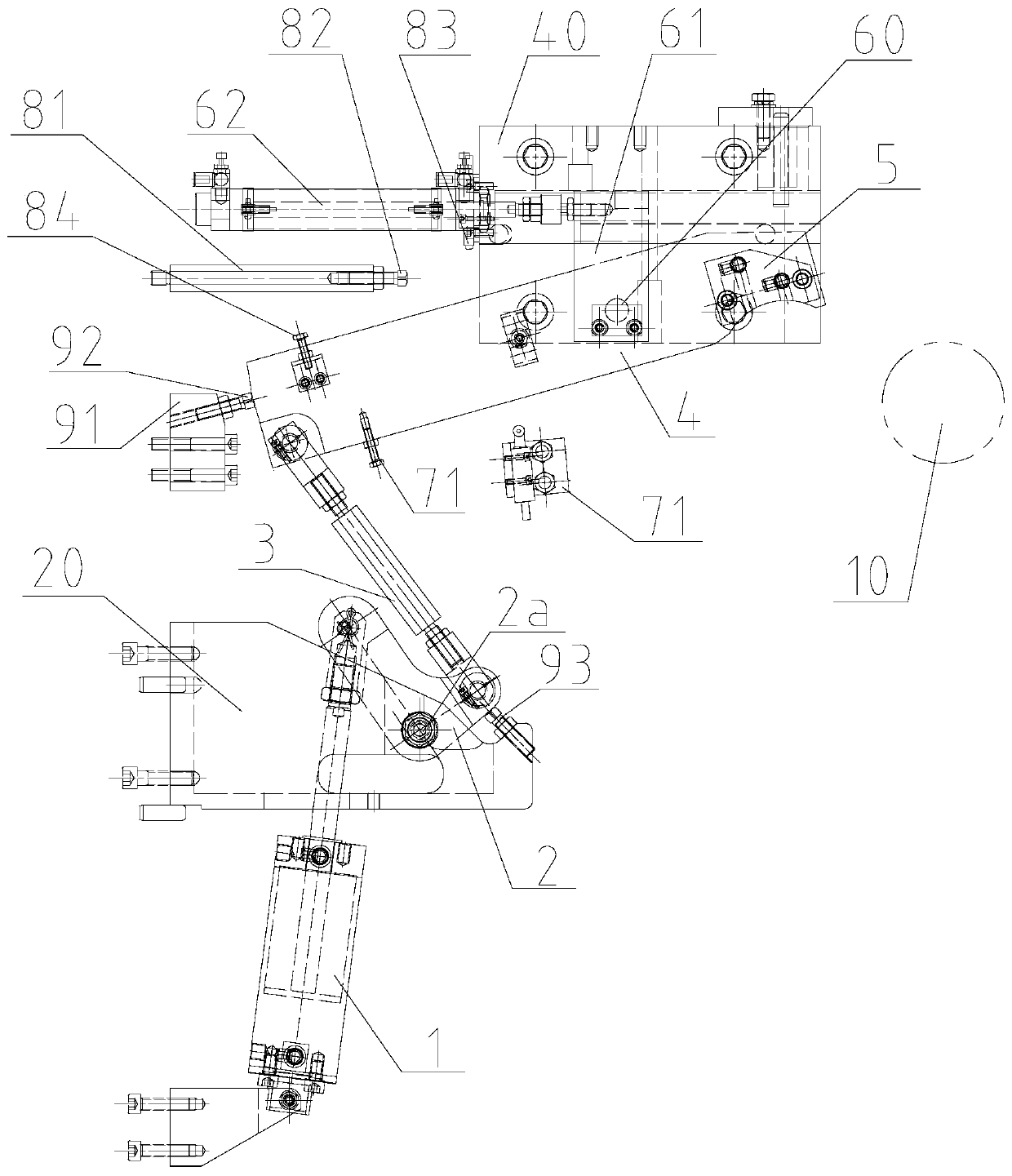
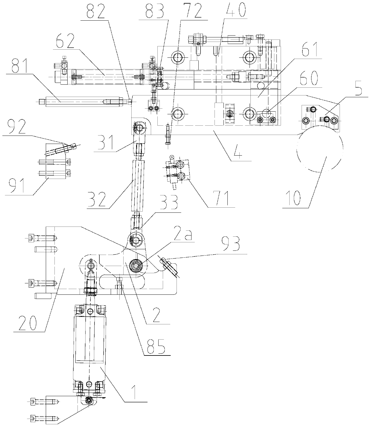
[0016] see figure 1 and figure 2 , the shaft head pressing device for replacing the printing plate cylinder sleeve of the present invention is installed on the drive side wallboard for installing the fixed end shaft head 10 of the plate cylinder and includes a clutch cylinder 1, a first bracket 2, a connecting rod 3. The compression mechanism, displacement mechanism, position detection mechanism, compression stop mechanism and opening stop mechanism of the second bracket 4 and the briquetting block 5; wherein,

[0017] The bottom end of the clutch cylinder 1 is hinged on the drive side wall plate;

[0018] The first support 2 is composed of a vertical arm and a transverse arm and is L-shaped. The rotating shaft 2a of the first support 2 is located at the junction of the vertical arm and the transverse arm and is hinged on the driving side wall plate through the first fix...


PUM


Abstract

The invention discloses a shaft head pressing device for replacing a printing plate cylinder sleeve. The shaft head pressing device comprises a pressing mechanism, a displacement mechanism and a position detection mechanism, wherein the pressing mechanism comprises a clutch cylinder, a first support, a connecting rod, a second support and a pressing block; a rotating shaft of the first support ishinged to the upper portion of the clutch cylinder, and one end of the first support is hinged with a piston rod of the clutch cylinder; the lower end of the connecting rod is hinged with the other end of the first support; the lower rear end of the second support is hinged with the upper end of the connecting rod; the pressing block is fixed at the lower front part of the second support; the displacement mechanism comprises a second fixed seat arranged on one side of the second support, a displacement block arranged in a movement groove of the second fixed seat and hinged with the second support through a rotary shaft, and a displacement cylinder connected with the rear end of the displacement block; and the position detection mechanism comprises a position sensor arranged below the rearportion of the second support, and a position sensing piece arranged at the lower rear end of the second support. The shaft head pressing device not only can reduce the degree of disturbance of a coreshaft of a printing plate cylinder, but also can save space.

Description

technical field [0001] The invention relates to a shaft head pressing device for replacing a printing plate cylinder sleeve. Background technique [0002] Since there are more and more printed materials of various specifications, printing machines must also adapt to this demand. To change the printing format on a printing press, it is usually necessary to change the diameter of the plate cylinder, that is, to change the sleeve of the plate cylinder. When replacing the sleeve, the arm bracket connected with the shaft head of the plate cylinder is usually opened on the operation side wall plate, and the drive side shaft head of the cylinder mandrel is fixedly supported in the drive side wall plate. Since the arm frame at the operating side end of the printing plate cylinder is opened, the mandrel of the cylinder is actually a cantilever beam structure fixed on one side. Since the cylinder is very heavy, it will produce a large deflection, so that the loose end of the cylinder...

Claims


Application Information

Patent Timeline
IPC IPC(8): B41F27/14
CPCB41F27/14
Inventor 全代伦彭勇瞿维国焦永志张川肖虎
Owner GOSS GRAPHIC PRINTING SYST CHINA
Why Eureka
Try Eureka