A friction wheel movement mechanism and on-orbit inspection device exposed outside the material cabin
A technology of motion mechanism and friction wheel, which is applied in transportation and packaging, aerospace equipment, tools, etc., and can solve the problems of large drive device size, pressure difference, and optical performance degradation
- Summary
- Abstract
- Description
- Claims
- Application Information
AI Technical Summary
Problems solved by technology
Method used
Image
Examples
Embodiment 1
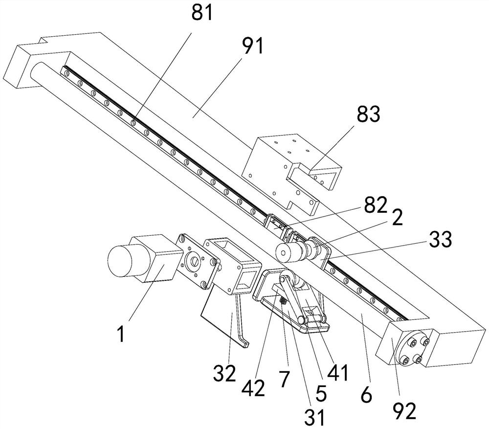
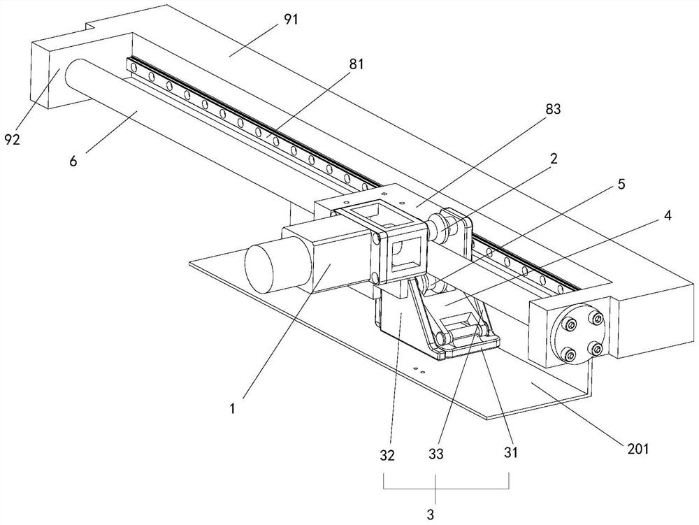
[0079] like Figure 1-4 As shown, a friction wheel movement mechanism exposed outside the cabin of a material, including:
[0080] drive mechanism 1,
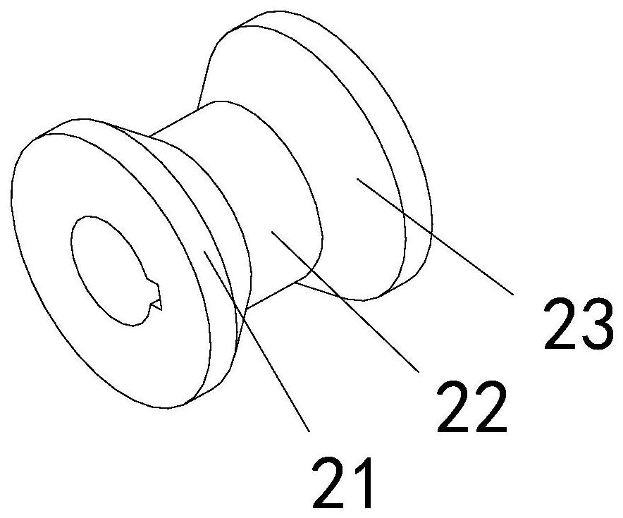
[0081] The active friction wheel 2 is fixedly installed on the output shaft of the drive mechanism 1;
[0082] The active pre-tightening base 3, the output shaft of the driving mechanism 1 and one end of the active pre-tightening base 3 are rotated and installed;
[0083] Driven pre-tightening base 4, one end of driven pre-tightening base 4 and the other end of active pre-tightening base 3 are rotated and installed, and the other end of driven pre-tightened base 4 is rotated and installed with driven friction wheel 5; The friction wheel 2 is arranged in parallel;
[0084] The friction rod 6 is sandwiched between the active friction wheel 2 and the driven friction wheel 5 components, and frictionally cooperates with the active friction wheel 2 and the driven friction wheel 5 respectively;
[0085] Preload spring 7, preload s...
Embodiment 2
[0107] like Figure 4 As shown, an optical space on-orbit inspection device includes an inspection mechanism 100 and the above-mentioned material external exposure friction wheel movement mechanism, and the material external exposure friction wheel movement mechanism and the inspection mechanism 100 are both the same as the inspection mechanism 100. The exposed surface of the material is parallel, and the inspection mechanism 100 is fixedly connected with the movement mechanism of the friction wheel exposed outside the material cabin. The optical imaging module 101 is slidably installed on the inspection mechanism 100 , and the sliding direction of the optical imaging module 101 is perpendicular to the friction rod 6 .
[0108] Preferably, the structure of the inspection mechanism 100 is exactly the same as that of a friction wheel movement mechanism exposed outside the cabin of a material. The installation base 91 of the inspection mechanism 100 is fixedly connected with the ...
PUM
 Abstract
Description
Claims
Application Information
 - R&D Engineer
- R&D Manager
- IP Professional
- Industry Leading Data Capabilities
- Powerful AI technology
- Patent DNA Extraction
Browse by: Latest US Patents, China's latest patents, Technical Efficacy Thesaurus, Application Domain, Technology Topic, Popular Technical Reports.
© 2024 PatSnap. All rights reserved.Legal|Privacy policy|Modern Slavery Act Transparency Statement|Sitemap|About US| Contact US: help@patsnap.com


