Turbine blade honeycomb spiral cavity cooling structure

A technology for turbine blades and cooling structures, applied in the direction of blade support components, air transportation, engine functions, etc., can solve the problems of large flow resistance, difficult manufacturing, complex structure, etc., improve the efficiency of the whole machine, eliminate mutual impact and Good blending and body-fitting effect

Active Publication Date: 2020-04-28
DALIAN UNIV OF TECH
View PDF6 Cites 14 Cited by
  • Summary
  • Abstract
  • Description
  • Claims
  • Application Information

AI Technical Summary

Problems solved by technology

The main feature of this solution is that it can organically couple heat conduction, convective cooling, impingement cooling and film cooling together. It has the advantages of large heat exchange area and full utilization of cold air, but it also has complex structure, difficult manufacturing, Disadvantages such as large flow resistance and weak strength

Method used


Image

  • Turbine blade honeycomb spiral cavity cooling structure
  • Turbine blade honeycomb spiral cavity cooling structure
  • Turbine blade honeycomb spiral cavity cooling structure

Examples


Embodiment 1

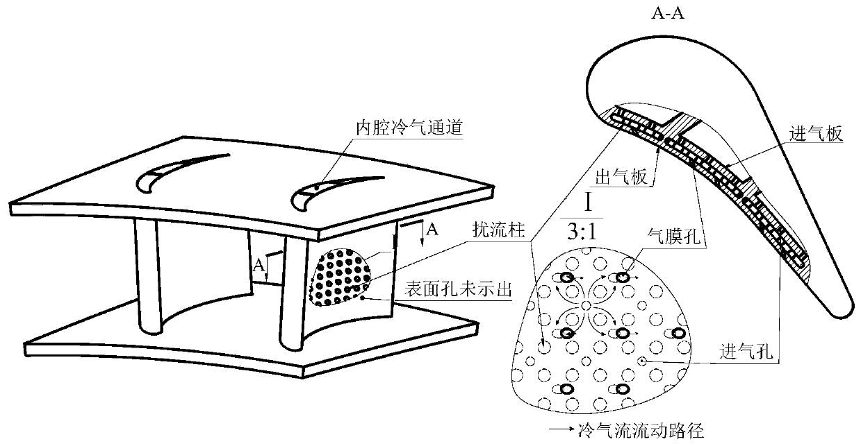
[0041] The present invention conducts a comparative study on the internal cooling air flow state of the conventional laminate structure and the honeycomb spiral cavity structure in the present invention through three-dimensional numerical simulation, as shown in Figure 7 (a) and Figure 7 (b) comparative analysis, it can be known that the present invention The cross-sectional area of ​​the intercooler air channel is roughly the same along the way, there will be no flow abruptness and throttling, and the airflow turning angle is small and there is no mutual impact and mixing, so the resistance of the relative laminate structure is smaller.

Embodiment 2

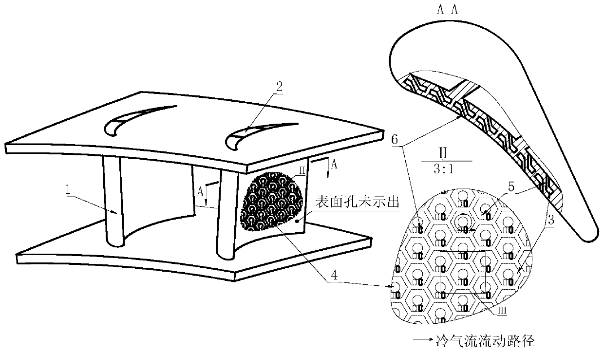
[0043] As shown in Figure 2, the cooling structure of the turbine blade honeycomb spiral cavity includes a hollow turbine blade 1, a honeycomb spiral cavity 3 and a spoiler column 4;

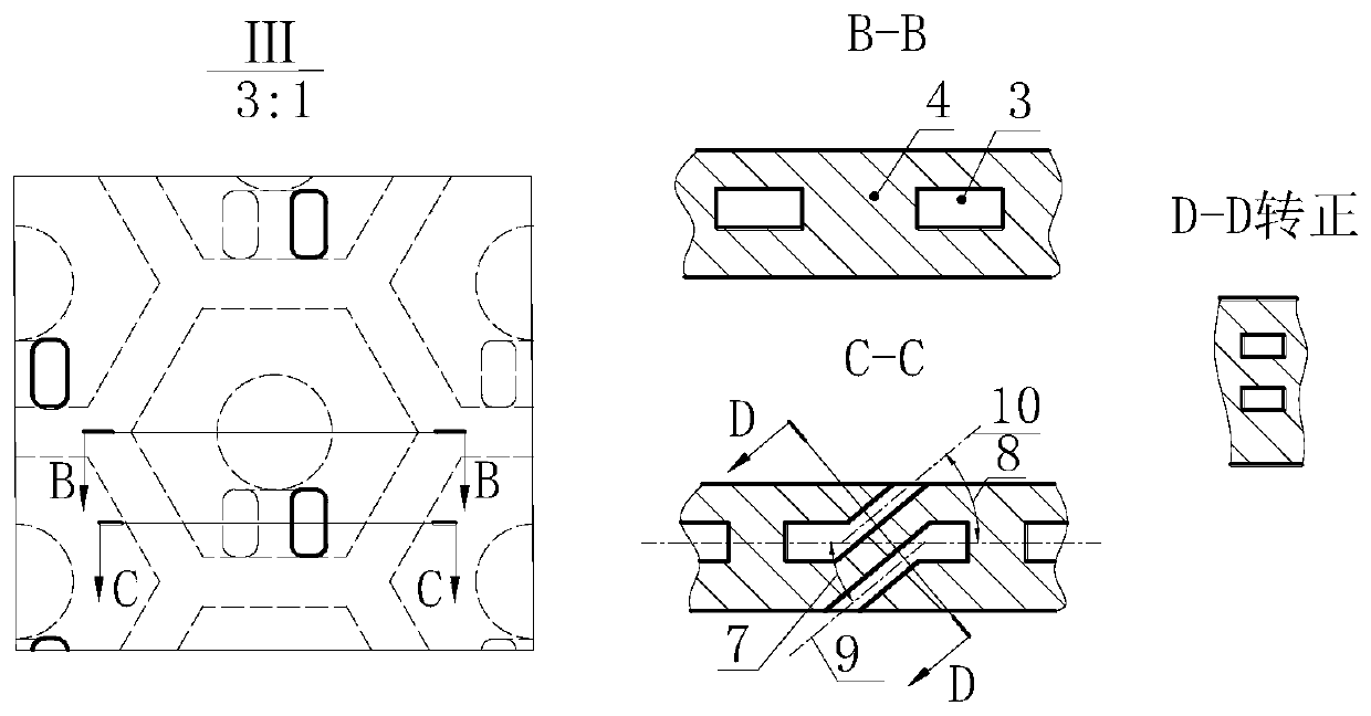
[0044] The inside of the hollow turbine blade 1 is provided with a cold air channel 2, and a plurality of arrays of honeycomb spiral chambers 3 are arranged in the blade wall of the hollow turbine blade 1, and the center of the honeycomb spiral chamber 3 is provided with a spoiler column 4, and the spoiler column 4 is a cylindrical structure, each honeycomb spiral chamber 3 is a unit body, each honeycomb spiral chamber 3 is approximately regular hexagonal in shape, and a plurality of unit bodies are arranged in a honeycomb shape, and in each unit body, the air intake The hole 5 and the air outlet hole 6 are respectively located on both sides of the blade wall, and the centerline 9 of the air inlet hole and the centerline 10 of the air outlet hole are parallel in the same vertical plane. The cros...

Embodiment 3

[0046] The cooling structure of the turbine blade honeycomb spiral cavity includes a hollow turbine blade 1, a honeycomb spiral cavity 3 and a spoiler column 4; the inside of the hollow turbine blade 1 is provided with a cold air passage 2, and the blade wall of the hollow turbine blade 1 is provided with There are multiple arrays of honeycomb spiral chambers 3, and the center of the honeycomb spiral chamber 3 is provided with a spoiler column 4. The spoiler column 4 is a cylindrical structure, and each honeycomb spiral chamber 3 is a unit body, and each honeycomb spiral chamber 3 is shaped like a square In each unit body, the air inlet 5 and the air outlet 6 are respectively located on both sides of the blade wall, and the centerline 9 of the air inlet and the centerline 10 of the air outlet parallel in the same vertical plane. The included angles between the central line 9 of the air inlet hole and the central line 10 of the air outlet hole and the horizontal plane are the i...


PUM


Abstract

The invention belongs to the technical field of turbine cooling of aero-engines and gas turbines, and relates to a turbine blade honeycomb spiral cavity cooling structure. The turbine blade honeycombspiral cavity cooling structure involves hollow turbine blades, honeycomb spiral cavities and turbulence columns, wherein cooling air channels are arranged in the hollow turbine blades, and the cooling air channels are used for allowing low-temperature cooling air to flow in the blades to cool the blades; the plurality of honeycomb spiral cavities which are arranged in arrays are arranged in the blade wall surfaces of the hollow turbine blades for allowing the cooling air to enter and carry out convection cooling; the centers of the honeycomb spiral cavities are provided with turbulence columns which are in a cylindrical structure; and in each unit body, air inlet holes and air outlet holes are positioned in the two sides of the blade wall surfaces correspondingly, and the central lines ofthe air inlet holes and the central lines of the air outlet holes are parallel in the same vertical plane. According to the cooling structure, the number of structural elements per unit area can be increased by about 15%, the flow resistance and loss of the cooling air are reduced by about 10%-15%, and then the efficiency of the whole engine is improved.

Description

technical field [0001] The invention belongs to the technical field of turbine cooling for aero-engines and gas turbines, and relates to a cooling structure for a honeycomb spiral cavity of a turbine blade. Background technique [0002] In the current field of aero-engine and gas turbine technology, the measures taken to improve device efficiency are usually to increase the gas temperature before the turbine. However, the tolerance limit of the materials currently used is far lower than the ambient temperature of the gas, so the cooling of the turbine blades has attracted much attention. . The current cooling measures for turbine blades are generally internally enhanced convective heat transfer and externally formed air film insulation. The principle of the cooling design is to use the least amount of cold air to take away as much heat as possible to protect components in a lower temperature range. , and has a small temperature gradient. Specifically, the hollow design is a...

Claims


Application Information

Patent Timeline
Patent Type & Authority Applications(China)
IPC IPC(8): F01D5/18
CPCF01D5/187F01D5/188F01D5/186F05D2250/25F05D2250/132F05D2260/202F05D2260/204F05D2260/22141F01D5/18F05D2220/32
Inventor 吕东李海旺韦文涛王楠孔星傲
Owner DALIAN UNIV OF TECH
Why Eureka
Try Eureka