Speed reducer structure

A reducer and housing technology, applied in the field of reducer structure, can solve the problems of short service life and poor transmission accuracy of the reducer, achieve large axial bearing capacity, not easy to move axially, and increase the service life

Pending Publication Date: 2020-04-28
浙江通宇变速机械股份有限公司
View PDF0 Cites 3 Cited by
  • Summary
  • Abstract
  • Description
  • Claims
  • Application Information

AI Technical Summary

Problems solved by technology

[0006] The purpose of the present invention is to solve the above problems in the existing technology, and propose a reducer structure. The technical problem to be solved by the present invention is: how to solve the problems of poor transmission accuracy and short service life of the existing reducer

Method used


Image

  • Speed reducer structure
  • Speed reducer structure
  • Speed reducer structure

Examples


Embodiment Construction

[0029] The following are specific embodiments of the present invention and in conjunction with the accompanying drawings, the technical solutions of the present invention are further described, but the present invention is not limited to these embodiments.

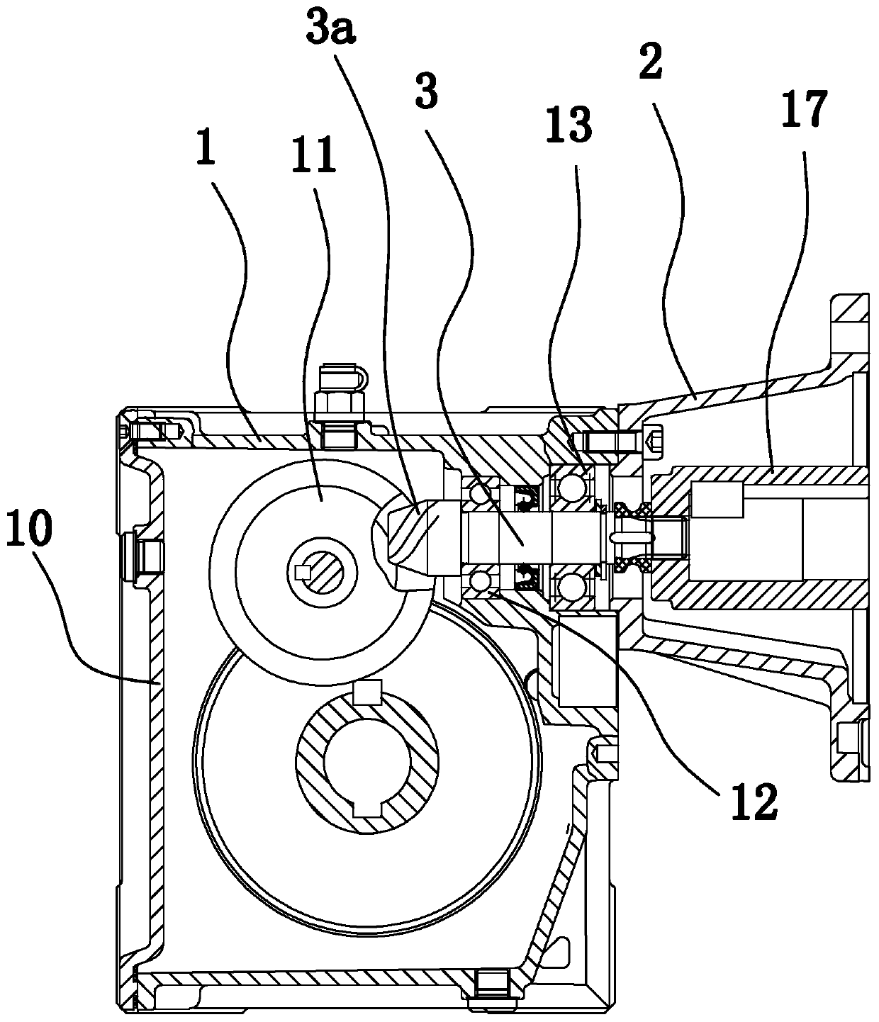
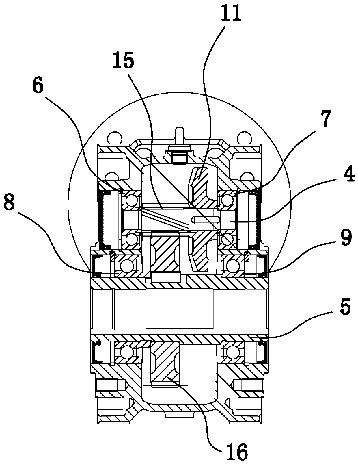
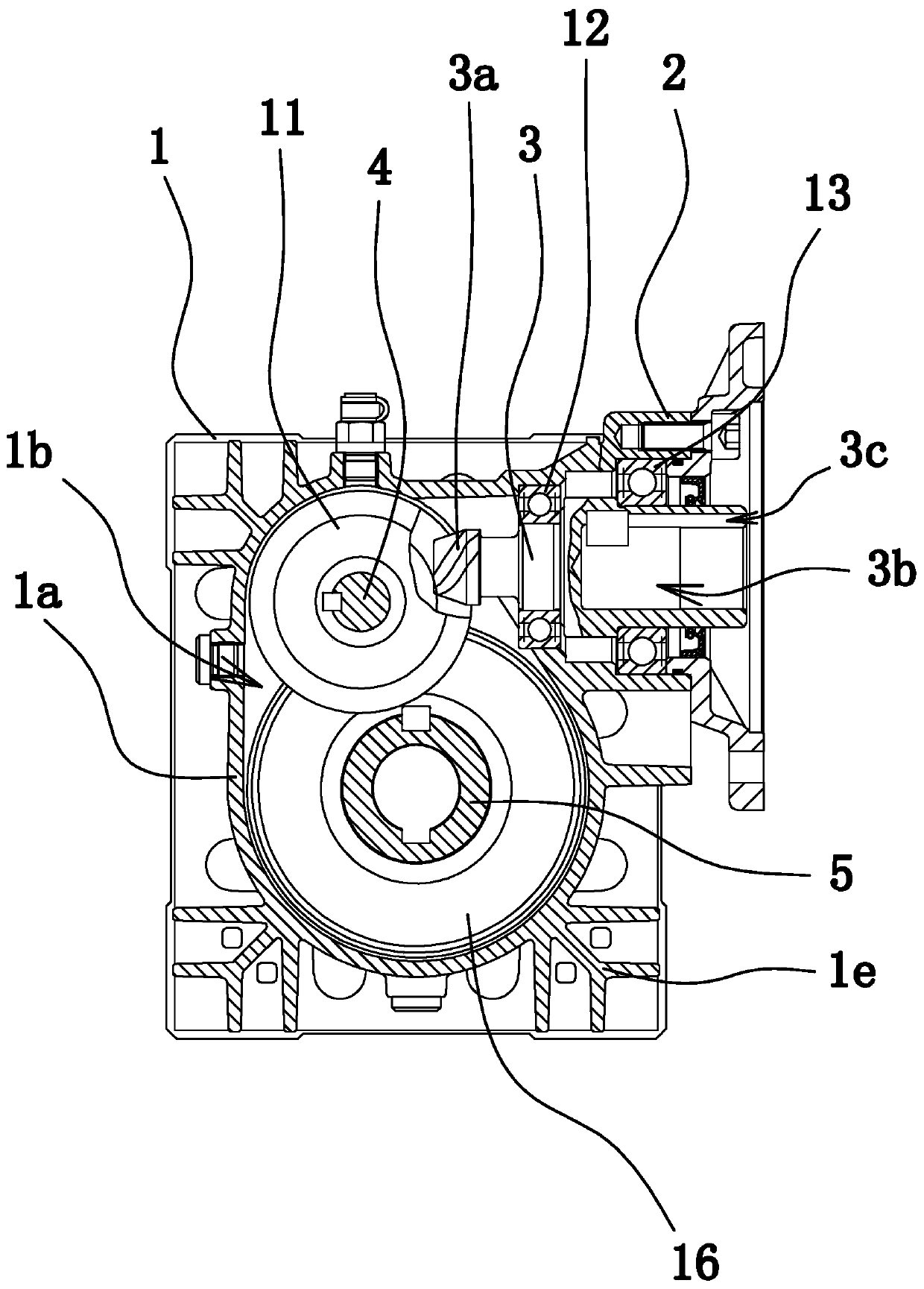
[0030] Such as Figure 3-6 As shown, the reducer structure includes a housing 1, a flange 2, an input shaft 3, a transmission shaft 4, an output shaft 5, a large gear 16 and a pinion 15, and the flange 2 is fixed on the housing 1 for installing the motor .

[0031] Specifically, the two ends of the input shaft 3 are rotatably connected in the housing 1 through bearing five 12 and bearing six 13 respectively, and the input shaft 3 has a shaft hole 3b for the motor shaft to penetrate, and a spline groove is provided in the shaft hole 3b 3c, compared with the existing reducer structure, the coupling 17 structure is omitted, so that the input shaft 3 can be made relatively larger, and the bearing five 12 and bearing six 13 us...


PUM


Abstract

The invention provides a speed reducer structure, which belongs to the technical field of machinery, and solves the problems that an existing speed reducer is poor in transmission precision and is short in service life. The speed reducer structure comprises a housing, a flange, an input shaft, a transmission shaft and an output shaft, wherein the two ends of the transmission shaft are separately connected in the housing through a bearing I and a bearing II; the two ends of the output shaft are separately connected in the housing through a bearing III and a bearing IV; a coaming is arranged inthe housing, and a mounting cavity is enclosed in the housing; an opening is formed in the end surface of the housing, and the edge of the opening is detachably connected with an end cover; both the bearing I and the bearing III are arranged on the end cover; both the transmission shaft and the output shaft are positioned in the mounting cavity; a hypoid gear is arranged on the input shaft; a bevel gear which is engaged with the hypoid gear is arranged on the transmission shaft; and the dimension of the bearing II is greater than that of the bearing I. The bearing II can bear greater axial bearing force relative to the bearing I, so that stable and consistent transmission efficiency can be kept, and therefore, the speed reducer structure has relatively high transmission precision, and theservice life of the speed reducer structure is prolonged.

Description

technical field [0001] The invention belongs to the technical field of machinery and relates to a reducer structure. Background technique [0002] The reducer is an independent component composed of gear transmission, worm transmission, and gear-worm transmission enclosed in a rigid shell. It is often used as a reduction transmission device between the prime mover and the working machine. It plays the role of matching speed and transmitting torque between prime mover and working machine or actuator, and is widely used in modern machinery. [0003] Such as figure 1 and figure 2 As shown, the existing helical-bevel gear reducer includes a housing 1 and a large gear 16, a pinion 15, a transmission shaft 4, an input shaft 3, a hypoid gear 3a, and a bevel gear all arranged in the housing 1. The gear 11 and the output shaft 5, the housing 1 is square, and the side of the housing 1 is provided with a flange 2 for the installation of the motor. The small gear 15 and the bevel g...

Claims


Application Information

Patent Timeline
Patent Type & Authority Applications(China)
IPC IPC(8): F16H57/02F16H57/021F16H57/023F16H57/029F16H57/031F16H57/038
CPCF16H57/02F16H57/021F16H57/023F16H57/029F16H57/031F16H57/038F16H2057/02008F16H2057/02034F16H2057/02086F16H2057/0235
Inventor 徐忠法唐礼明
Owner 浙江通宇变速机械股份有限公司
Why Eureka
Try Eureka