Fiber-optic gyroscope system based on 60-micron optical fiber and optical fiber welding method

A fiber optic gyroscope and fiber splicing technology, applied in the coupling of optical waveguides, Sagnac effect gyroscopes, gyroscopes/steering sensing devices, etc., can solve the problem of very high volume requirements

Active Publication Date: 2020-04-28
HEBEI HANGUANG HEAVY IND
View PDF9 Cites 3 Cited by
  • Summary
  • Abstract
  • Description
  • Claims
  • Application Information

AI Technical Summary

Problems solved by technology

With the continuous expansion of the application field of fiber optic gyroscopes, especially in the application of tactical missiles, rockets, artillery, and drones, the system has lower requirements for the accuracy of fiber optic gyroscopes, but has very high requirements for its volume. Light source, Y waveguide, Couplers, detectors and other devices, under the same performance index, have reached the limit in volume, and only by optimizing the size of the fiber ring can the miniaturization of the fiber optic gyroscope be achieved.

Method used


Image

  • Fiber-optic gyroscope system based on 60-micron optical fiber and optical fiber welding method
  • Fiber-optic gyroscope system based on 60-micron optical fiber and optical fiber welding method
  • Fiber-optic gyroscope system based on 60-micron optical fiber and optical fiber welding method

Examples


Embodiment Construction

[0030] The present invention will be described in detail below with reference to the accompanying drawings and examples.

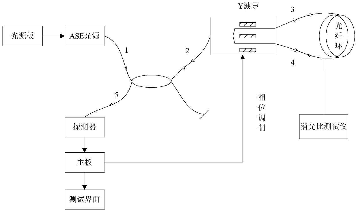
[0031] The present invention provides a fiber optic gyroscope system based on 60um optical fiber, such as figure 1 As shown, the fiber optic ring in the fiber optic gyroscope is a fiber optic ring wound with 60um fiber;

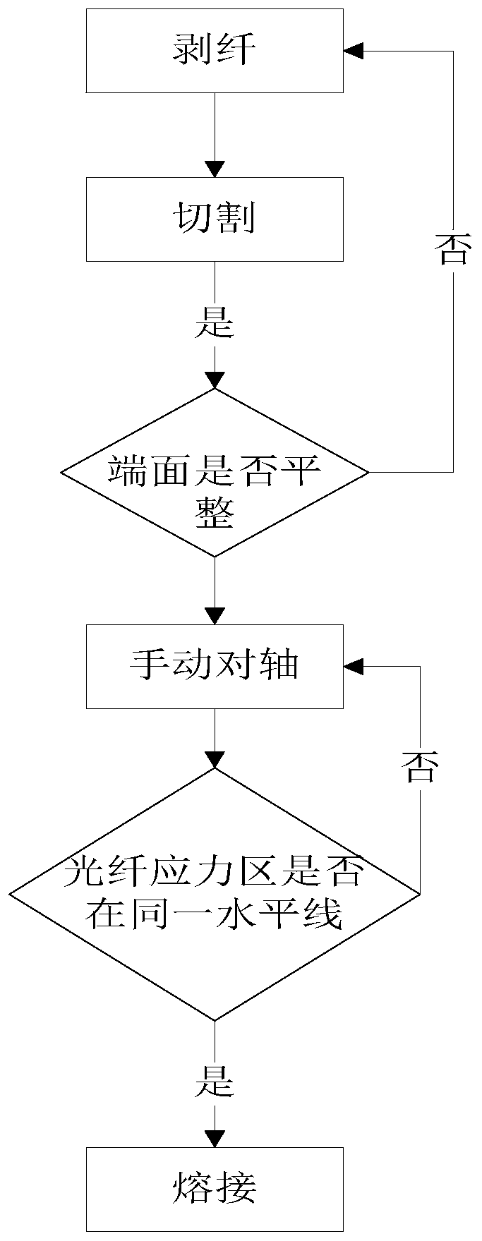
[0032] The waveguide output ends of the Y waveguide in the fiber optic gyroscope are all 80 waveguide fibers; the fiber ring and the 80 waveguide fibers at the two waveguide output ends of the Y waveguide are fused manually on the axis. The discharge capacity is 180bit, and the discharge parameter is modified to 1800ms.

[0033] In the embodiment of the present invention, the fiber optic gyroscope includes a light source board, an ASE light source, a 2×2 fiber coupler, a Y waveguide, a detector, and a main board.

[0034] The light source board is used to drive the ASE light source to emit light signals.

[0035] The optical signal ent...


PUM

PropertyMeasurementUnit
The inside diameter ofaaaaaaaaaa
Outer diameteraaaaaaaaaa

Abstract

The invention discloses a fiber-optic gyroscope system based on a 60-micron optical fiber and an optical fiber welding method. According to the invention, a sensitive optical fiber ring formed by winding 60 optical fibers is used and a set of high-precision fiber-optic gyroscope is built, wherein the size of the fiber-optic ring is phi 96.5 * phi 109.5 * 16.5 (the inner diameter * the outer diameter * the thickness), the length of the fiber-optic ring is about 3400 m, and the theoretical precision of the fiber-optic ring can reach 0.0005 degree / h compared with an 80 fiber-optic ring (2500 m) with the same volume. A light source with a tail fiber of 80 or 125, a Y waveguide, a coupler and a detector are continuously used, and the solution to a problem of welding matching of a 60 optical fiber ring and the 80 waveguide is the key. An FSM-100P polarization-maintaining welding machine from the Fujikura and an ERM-102 extinction ratio tester of a GP company are used for manually aligning and welding 60 optical fibers and 80 waveguide fibers, the extinction ratio of the 60 optical fibers and the 80 waveguide fibers is tested, and the extinction ratio is compared with an extinction ratioof 80 optical fiber rings and 80 waveguide fibers. Connection of the whole fiber-optic gyroscope system is completed, and the zero-bias stability of the fiber-optic gyroscope system is tested. According to the invention, the matching problem of 60 optical fiber and 80 optical fiber devices is solved, and the selection of devices for manufacturing gyroscopes is more flexible.

Description

technical field [0001] The invention relates to the field of optical fiber technology, in particular to an optical fiber gyroscope system based on a 60um optical fiber and an optical fiber fusion splicing method. Background technique [0002] The fiber optic gyroscope is a sensor for measuring the angular velocity of the carrier. It is mainly composed of five optical devices: an optical fiber ring, a light source, a Y waveguide, a coupler and a detector. The technology is relatively mature, and there are matching testing equipment and welding machines. With the continuous expansion of the application field of fiber optic gyroscopes, especially in the application of tactical missiles, rockets, artillery, and drones, the system has lower requirements for the accuracy of fiber optic gyroscopes, but has very high requirements for its volume. Light source, Y waveguide, Couplers, detectors and other devices, under the same performance index, have reached the limit in size, and on...

Claims


Application Information

Patent Timeline
IPC IPC(8): G01C19/72G02B6/255
CPCG01C19/725G02B6/2551
Inventor 胡文纲张红杰
Owner HEBEI HANGUANG HEAVY IND
Why Eureka
Try Eureka