A waste gas treatment device

A technology of waste gas treatment device and dust removal device, which is applied in the direction of combination device, separation method, combustion type, etc., which can solve the problems of easy clogging of zeolite runners, many harmful substances, and reduced adsorption capacity, and achieve the effect of avoiding frequent replacement of filter materials

Active Publication Date: 2021-10-15
JIANGSU EAST STEEL
View PDF9 Cites 0 Cited by
  • Summary
  • Abstract
  • Description
  • Claims
  • Application Information

AI Technical Summary

Problems solved by technology

[0003] At present, the most common treatment equipment on the market is a device formed by a zeolite rotor combined with a combustion furnace. Because there are many dust particles in the exhaust gas, the device of the zeolite rotor combined with a combustion furnace is usually only filtered by an ordinary pre-filter device , there is no effective pretreatment of the exhaust gas, resulting in the frequent replacement of filter materials in the later purification device, which is time-consuming and laborious, and it is easy to cause the zeolite runner to be easily blocked
At the same time, the cooling air used in the cooling zone of the zeolite runner in the current zeolite wheel concentration treatment device is basically untreated raw waste gas, so that when the zeolite runner passes through the cooling zone, it will absorb some harmful substances, and when it reaches the adsorption zone, Its adsorption capacity has decreased, which will inevitably cause relatively more harmful substances in the gas discharged from the adsorption area.

Method used


Image

  • A waste gas treatment device
  • A waste gas treatment device
  • A waste gas treatment device

Examples


Embodiment Construction

[0020] In order to make the purpose, technical solutions and beneficial effects of the present invention more clear, the preferred embodiments of the present invention will be described in detail below in conjunction with the accompanying drawings, so as to facilitate the understanding of technical personnel.

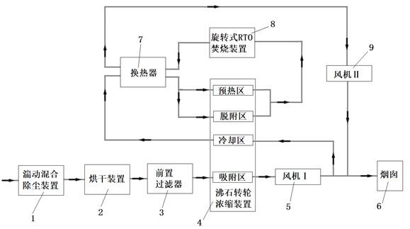
[0021] Such as figure 1 As shown, a waste gas treatment device includes a turbulent mixing dust removal device 1, a drying device 2, a pre-filter 3, a zeolite runner concentration device 4, a fan I 5, a chimney 6, a heat exchanger 7, and a rotary RTO incineration device 8. Fan II 9, the air outlet of the turbulent mixing dust removal device 1 is connected to the air inlet of the drying device 2 through the air pipe, and the air outlet of the drying device 2 is connected to the air inlet of the pre-filter 3 through the air pipe , the air outlet of the pre-filter 3 is connected to the air inlet of the adsorption area of ​​the zeolite runner concentration device 4 through ...


PUM


Abstract

The invention relates to a waste gas treatment device, which belongs to the technical field of environmental protection equipment, including a turbulent mixing dust removal device, a drying device, a pre-filter, a zeolite runner concentration device, a fan I, a chimney, a heat exchanger, and a rotary RTO incinerator Device, blower II, the present invention pretreats the waste gas through the turbulent mixing dust removal device installed in front of the pre-filter, removes the particulate matter in the waste gas, and then filters the residual dust in the waste gas through the pre-filter In this way, it can avoid frequent replacement of the filter material of the pre-filter, and avoid the clogging of the zeolite runner concentrator due to the poor filtering effect of the pre-filter; at the same time, the present invention is to process the gas in the adsorption area of ​​the zeolite runner As the cooling gas in the cooling zone, avoid using the original exhaust gas as the cooling gas, which will cause the zeolite runner to absorb certain organic harmful substances when it reaches the cooling zone, and cause the adsorption capacity of the zeolite runner to decrease when it reaches the adsorption zone, resulting in excessive harmful substances in the exhaust gas.

Description

technical field [0001] The invention belongs to the technical field of environmental protection equipment, and in particular relates to a waste gas treatment device. Background technique [0002] Due to the increasingly serious environmental pollution, the emission indicators of organic waste gas are becoming more and more stringent, and the demand for environmental protection equipment is also increasing. [0003] At present, the most common treatment equipment on the market is a device formed by a zeolite rotor combined with a combustion furnace. Because there are many dust particles in the exhaust gas, the device of the zeolite rotor combined with a combustion furnace is usually only filtered by an ordinary pre-filter device , there is no effective pretreatment of the exhaust gas, resulting in frequent replacement of the filter material in the later purification device, which is time-consuming and laborious, and it is easy to cause the zeolite runner to be easily blocked....

Claims


Application Information

Patent Timeline
Patent Type & Authority Patents(China)
IPC IPC(8): B01D53/06B01D50/00F23G7/06
CPCB01D53/06F23G7/06F23G2209/14B01D50/10
Inventor 汤红海
Owner JIANGSU EAST STEEL
Why Eureka
Try Eureka