Dual-power-supply type tourism rail transit system

A rail transit and dual power supply technology, applied in the field of rail transit systems, can solve the problems of poor adaptability of long-term tourist rail transit lines, it is difficult to meet the power demand of a single operating section, and vehicles are not allowed to stop and charge, so as to save maintenance work Quantity, construction cost savings, simple structure

Pending Publication Date: 2020-05-01
CHINA RAILWAY ERYUAN ENG GRP CO LTD
View PDF0 Cites 1 Cited by
  • Summary
  • Abstract
  • Description
  • Claims
  • Application Information

AI Technical Summary

Problems solved by technology

For long-distance tourist traffic lines, due to the large distance between stations, the electric energy that can be provided by a simple non-contact power supply is difficult to meet the electricity demand of a single operating section; and in a single section, vehicles are not allowed to park and charge; the entire line The pull-through contact power supply method will divide the natural landscape, affect environmental protection, and form a certain shelter for viewing due to the installation of columns, "spider web"-like contact nets or contact rails that are always pulled through
It can be seen that the existing contact power supply and non-contact power supply types are slightly less adaptable to the long-term tourist rail transit lines, and the introduction of a new power supply method is urgently needed

Method used


Image

  • Dual-power-supply type tourism rail transit system
  • Dual-power-supply type tourism rail transit system
  • Dual-power-supply type tourism rail transit system

Examples


Embodiment Construction

[0020] The present invention will be further described below in conjunction with the accompanying drawings and embodiments.

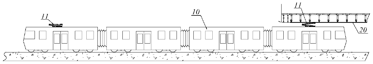
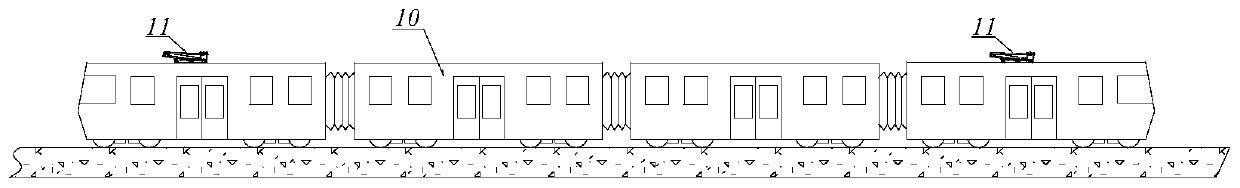
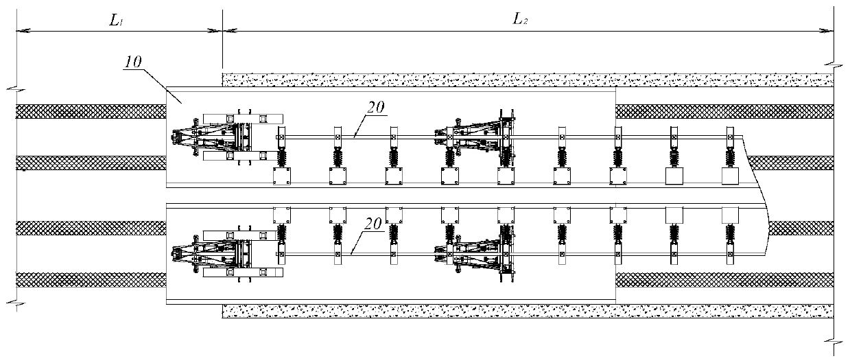
[0021] refer to figure 1 , figure 2 , image 3 and Figure 4 , a kind of dual power supply system tourist rail transit system of the present invention, comprises train 10 and the tourist rail transit system that is made up of open line section L1, tunnel section L2. The car body of the train 10 is provided with a storage battery pack or a supercapacitor pack to provide power for it to run on the open line section L1, and the top of the car body is provided with a pantograph 11 for it to smoothly take current from the catenary in the tunnel section L2, The pantograph 11 is equipped with rubber running wheels 12 that can meet the lifting requirements during train operation. In the tunnel section L2, a catenary 20 is erected on the top of the tunnel. The catenary 20 is provided with a non-electric section at the tunnel entrance and a live section in t...


PUM


Abstract

The invention relates to a dual-power-supply type tourism rail transit system, which aims to meet the requirements of power supply, viewing and travel speed of long and large tourism rail transit lines, reduce the damage of the tourism rail transit system to natural landscapes along the line to the greatest extent and improve the tourism experience of tourism trains. The system comprises a train and an open line segment and tunnel segment tourism rail transit system. A storage battery pack or a super capacitor pack for providing electric power for the train running on the open line segment isarranged in the train body, a pantograph for directly taking current from a contact net is arranged at the top of the train body in the tunnel segment, and a buffer device adapting to the lifting requirement in the train running process is arranged. Only a rail structure is laid on the open line section, no stand column or power supply line is arranged beside the line, and a train provides runningpower by itself. A contact net is erected at the top of the tunnel in the tunnel section; a contact net current collection switching device is arranged at an entrance and an exit of a tunnel section,the pantograph of the train is stably contacted with the contact net through the contact net current collection switching device after the train is driven into the tunnel section at a normal speed, and the contact net provides train running power and provides power for rapid charging of the storage battery pack or the super capacitor pack.

Description

technical field [0001] The invention relates to a rail transit system, in particular to a tourist rail transit system with dual power supply system. Background technique [0002] At present, the power supply methods of rail transit systems usually include contact power supply (catenary power supply, contact rail power supply), non-contact power supply (battery or super capacitor power supply, ground power supply). The rail transit system that adopts the contact power supply method is usually set up on the whole line. Regardless of the subgrade section, bridge section or tunnel section of the line, installation columns will be erected beside the track, and contact lines and contact rails with high voltage will be arranged along the line. It affects the viewing effect of the open line section, which is not conducive to environmental protection, and there is a certain risk of high voltage; during the operation of this system, the pantograph / catenary or power shoe / contact rail a...

Claims


Application Information

Patent Timeline
Patent Type & Authority Applications(China)
IPC IPC(8): B60L5/20B60L5/28B60L50/40B60L50/53B60M1/13
CPCB60L5/205B60L5/28B60L50/40B60L50/53B60L2200/26B60M1/13Y02T10/70
Inventor 徐银光李艳张茂帆姚小军王志强王孔明杨阳吴柯江钱科元吴晓魏德豪陈明
Owner CHINA RAILWAY ERYUAN ENG GRP CO LTD
Why Eureka
Try Eureka