Flat knitting machine steel wire conveying device

A technology of conveying device and steel wire, applied in textile and papermaking, weft knitting, knitting and other directions, can solve the problems of inability to block the calculation of wire conveying length, detachment, and the shedding of bottom needle loops, etc., to reduce the cost of knitting and labor costs. Effect

Pending Publication Date: 2020-05-01
NINGBO CIXING
View PDF1 Cites 6 Cited by
  • Summary
  • Abstract
  • Description
  • Claims
  • Application Information

AI Technical Summary

Problems solved by technology

However, in the above-mentioned device, the conveying length of the blocking wire cannot be calculated, and it is impossible to accurately judge whether the blocking wire has passed through all the starting needles. The coil falls off, or the blocking wire is conveyed too long, so that it is separated from the wire feeding mechanism, and a fault occurs

Method used


Image

  • Flat knitting machine steel wire conveying device
  • Flat knitting machine steel wire conveying device
  • Flat knitting machine steel wire conveying device

Examples


Embodiment Construction

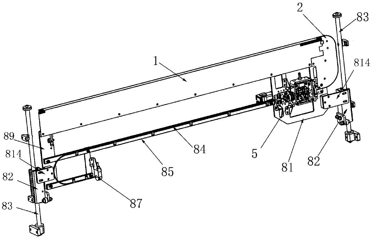
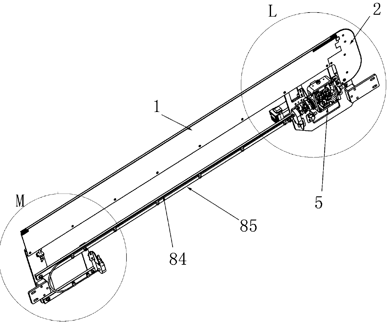
[0040] See attached picture. The lifting device described in this embodiment includes a threading plate assembly, a steel wire conveying assembly and a steel wire limiting assembly. The transmission and rotation of the steel wire is accomplished by the steel wire transmission assembly.

[0041]The threading plate assembly includes the threading plate 1, the lead plate 2 and the slotted needle plate connecting rod 3, the two ends of the threading plate assembly are installed on the left fixed plate 89 and the right fixed plate 81 respectively, and the lifting mechanism includes a linear bearing sleeve 82, a slide bar 83 and the lifting motor, the linear bearing sleeve 82 is installed on the slide bar 83, the lifting motor drives the linear bearing sleeve 82 to slide up and down along the slide bar 83, the left side fixed plate 89 and the right side fixed plate 81 are respectively installed on two sides by a connecting plate 814. On the linear bearing sleeve 82 on the side, the...


PUM


Abstract

The invention discloses a flat knitting machine steel wire conveying device which comprises a wire feeding motor and a gear box, wherein at least one set of wire feeding wheel and wire pressing wheelmatched with each other is arranged in the gear box, and the wire feeding wheel is driven by the wire feeding motor; a counting induction disc is fixed to a shaft of one wire feeding wheel, multiple pieces of first magnetic steel are uniformly arranged on the counting induction disc, and a third inductor matched with the first magnetic steel is arranged in the gear box; rotating shafts are arranged on the two sides of the gear box, sleeves through which a steel wire passes are arranged in the rotating shafts, a detouring gear is fixed to the rotating shaft on one side and meshed with a drivinggear on a bottom lifting motor, and the bottom lifting motor drives the gear box to turn over around the rotating shafts. The device works in cooperation with the bottom lifting needles on a bottom lifting plate; the length of the steel wire pushed forwards by the wire feeding wheel is calculated through the counting induction disc, and the condition that the steel wire penetrates through all thebottom lifting needles and cannot be disengaged from the wire feeding wheel.

Description

technical field [0001] The invention belongs to the technical field of knitting machinery, and in particular relates to a steel wire transmission device for a flat knitting machine. Background technique [0002] Because there is a certain distance between the mouth of the needle bed and the traction device in the flat knitting machine, that is to say, it is impossible for the woven piece to be clamped by the traction device immediately when it is woven. The woven piece under weaving (that is, the woven piece not clamped by the high roller) is uneven due to the lack of uniform traction, which affects the overall weaving effect of the woven piece, that is, only in the traction state can the woven fabric be smoothly The pieces are woven. Therefore, before entering the formal weaving of the knitted piece, it is first necessary to weave a starting fabric with a length of about 25-35mm. After the starting fabric is clamped by the high roller under the needle bed mouth, the knitte...

Claims


Application Information

Patent Timeline
Patent Type & Authority Applications(China)
IPC IPC(8): D04B15/00D04B15/90
CPCD04B15/00D04B15/90
Inventor 孙平范徐卫东李立军胡跃勇郑文玉
Owner NINGBO CIXING
Why Eureka
Try Eureka