Dyeing device for textile

A technology for dyeing and guiding fabrics, which is applied to the configuration of equipment for processing textile materials, processing textile material carriers, and spraying/jetting textile materials, etc. It can solve the problems of short residence time, slow rate of dye immersion into cloth, and slow dyeing rate. , to increase the residence time, improve the dyeing efficiency, and improve the dyeing rate.

Inactive Publication Date: 2020-05-01
吴盟
View PDF1 Cites 3 Cited by
  • Summary
  • Abstract
  • Description
  • Claims
  • Application Information

AI Technical Summary

Problems solved by technology

A new type of cloth dyeing device for textile machinery in the above-mentioned patent has certain shortcomings: in the process of dyeing the cloth, the cloth stays in the dye for a short time, the dyeing rate is slow

Method used


Image

  • Dyeing device for textile
  • Dyeing device for textile
  • Dyeing device for textile

Examples


Embodiment 1

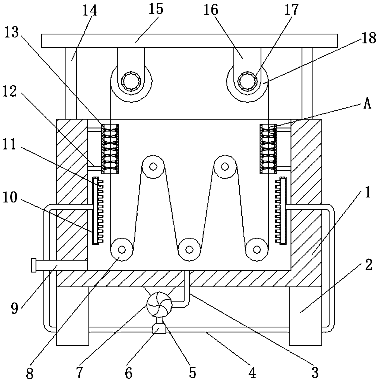
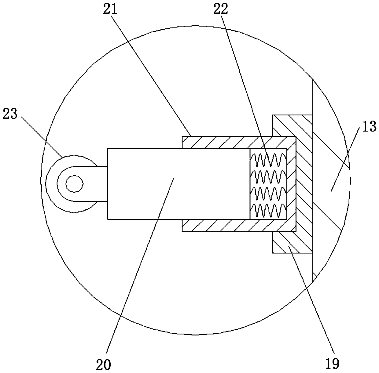
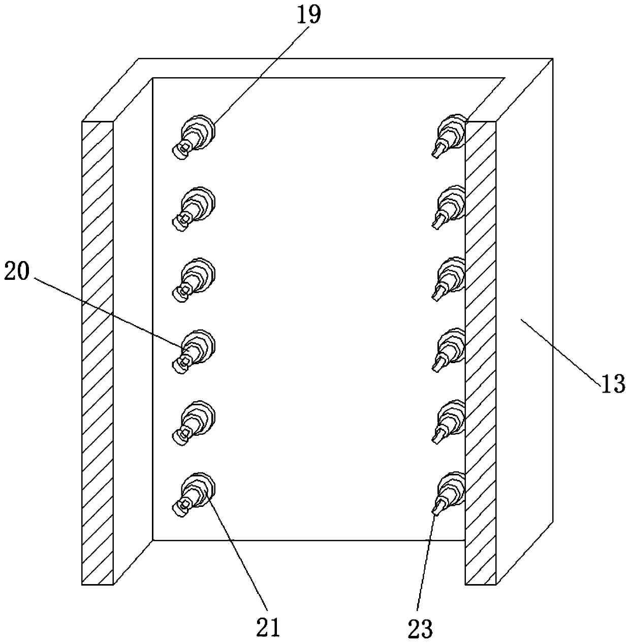
[0028] refer to Figure 1-4 , a textile dyeing device, comprising a dyeing box 1, the four corners of the top outer wall of the dyeing box 1 are welded with columns 14, and the top outer wall of the column 14 is welded with a top plate 15, and the bottom outer wall of the top plate 15 is close to both sides The positions of the fixed seats 16 are welded, and the number of the fixed seats 16 is two, and the outer wall of one side of the fixed seats 16 is connected with a motor 17 by bolts, and one end of the output shaft of the motor 17 is provided with a take-up roller 18, and the cloth dyeing box The inner wall of 1 is welded with equidistant and staggered horizontal bars, and the outer wall of the horizontal bar is rotatably connected with cloth guide roller 8, and the bottom outer wall of cloth dyeing box 1 is connected with water pump 7 by bolts, and one side of the outer wall of water pump 7 is connected by bolts. A suction pipe 3 is connected, one end of the suction pipe...

Embodiment 2

[0032] refer to Figure 5 , a cloth dyeing device for textile use. Compared with Embodiment 1, this embodiment also includes a blower 24 connected to the top outer wall of the dyeing box 1 by bolts, and an air guide pipe is arranged on one side of the outer wall of the blower 24 to guide the air. One end outer wall of the pipe is welded with a wind guide cover 25 .

[0033] Working principle: After dip-dyeing, you can open the liquid-changing tube 9 to export the dye, and then drive the motor 17 to work again, so that the cloth on the winding roller 18 is led to the other winding roller 18, and at the same time, the blower 24 is driven to work, which can be passed through the guide. The air cover 25 leads air and blows to the cloth, which effectively accelerates the air-drying speed of the cloth.


PUM


Abstract

The invention discloses a dyeing device for textile. The dyeing device comprises a dyeing box, wherein stand columns are correspondingly arranged at four corners of the outer wall of the top of the dyeing box; a top plate is welded to the outer walls of the tops of the stand columns; two fixing bases are correspondingly arranged at the positions, close to two sides, of the outer wall of the bottomof the top plate; a motor is connected to the outer wall of one side of the fixing base through bolts; a winding roller is arranged at one end of an output shaft of the motor; cross rods are equidistantly distributed on the inner wall of the dyeing box in a staggered mode; cloth guide rollers are rotationally connected to the outer walls of the cross rods; a water pump is connected to the outer wall of the bottom of the dyeing box through bolts; a water pumping pipe is connected to the outer wall of one side of the water pump through bolts; and one end of the water pumping pipe communicates with the dyeing box. According to the dyeing device, the staying time of cloth in the dyeing box can be effectively prolonged, so that the cloth dyeing efficiency is improved, the using effect is better; and dye can be immersed into the cloth more quickly, so that the dyeing rate of the device is further improved.

Description

technical field [0001] The invention relates to the technical field of textile dyeing, in particular to a textile dyeing device. Background technique [0002] Cloth dyeing machine is used for dyeing, bleaching, scouring and washing processes of woolen sweaters, acrylic and cotton sweaters, etc. It can also be used for bleaching and dyeing of gloves, socks, towels and other finished products. Ideal bleaching and dyeing equipment for finished products. [0003] After retrieval, the Chinese Patent Publication No. is CN209397374U, which discloses a novel cloth dyeing device for textile machinery, including a cloth dyeing box, a dye box, a heater, a switch door, an observation window, a base, a bracket and an air cleaner. A dye box is provided on the inner bottom side of the dyeing box, a heater is provided on the right side of the dye box, a switch door is provided on the surface of the dyeing box, and an observation window is provided on the surface of the switch door. A new ...

Claims


Application Information

Patent Timeline
IPC IPC(8): D06B1/02D06B23/04D06B23/20
CPCD06B1/02D06B23/04D06B23/20
Inventor 吴盟
Owner 吴盟
Why Eureka
Try Eureka