Gas leakage detector

A detector and gas technology, applied in the field of gas leak detectors

Pending Publication Date: 2020-05-01
西安古鲸电子技术有限公司
View PDF0 Cites 0 Cited by
  • Summary
  • Abstract
  • Description
  • Claims
  • Application Information

AI Technical Summary

Problems solved by technology

[0004] The purpose of the invention is to solve the problems of existing manual inspection Christmas trees

Method used


Image

  • Gas leakage detector
  • Gas leakage detector
  • Gas leakage detector

Examples


Embodiment 1

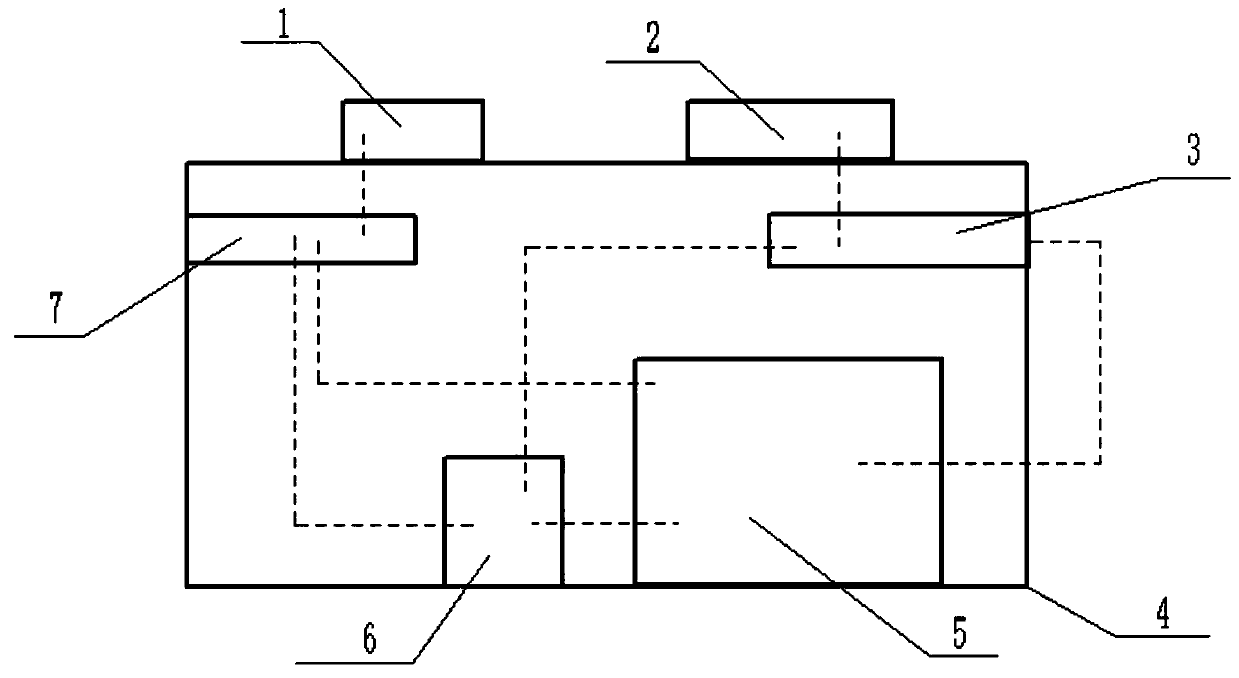
[0013] see figure 1 , this embodiment provides a gas leak detector, including: LED light emitting diode 1, photodiode 2, light emitting circuit 7, amplifier circuit 3, controller 6, battery assembly 5, housing 4; inside the housing 4 A cavity is provided; the controller 6, the battery assembly 5, the light-emitting circuit 7, and the amplifying circuit 3 are all set in the cavity; the LED light-emitting diode 1 and the photodiode 2 are all It is arranged on the outer surface of the housing 4 and kept on the same level; the LED light emitting diode 1 is connected to the output end of the light emitting circuit 7, and the input end of the amplifier circuit 3 is connected to the photodiode 2; the The battery assembly 5 is electrically connected to the input end of the light emitting circuit 7, the input end of the amplifying circuit 3, and the controller 6; the controller 6 is respectively connected to the input end of the light emitting circuit 7, the amplifying circuit 3; the ...


PUM


Abstract

The invention discloses a gas leakage detector. According to the gas leakage detector, based on a non-dispersive infrared technology theory, a light-emitting diode (LED) and a photodiode are arrangedthrough single-channel design, the LED emits a radiation wavelength corresponding to a gas absorption band, the photodiode detects an absorbed spectrum and converts the absorbed spectrum into an electrical signal, and a controller is applied to achieve control over a light-emitting circuit and feedback information processing of an amplification circuit. Simple and compact sensor design is applied,and in combination with autonomous low-consumption power supply, acceptable qualitative and quantitative analysis results are given.

Description

【Technical field】 [0001] The invention belongs to the field of energy production, and in particular designs a gas leakage detector. 【Background technique】 [0002] At present, the monitoring of wellhead data in various oil production plants in the oil field has basically realized the monitoring of pressure, power chart, and electric parameters. However, whether the oil production of the oil production tree is normal or not depends on manual inspection. Experience and professionalism. At present, some blocks are monitored by cameras, and the personnel in the monitoring room check remotely. If oil leakage occurs, the pumping units will be stopped immediately. However, the large number of oil wells and the high work intensity cannot realize intelligent monitoring. [0003] In order to solve the problem of manually inspecting Christmas trees, the invention provides a gas leakage detector. 【Content of invention】 [0004] The purpose of the invention is to solve the problem of ...

Claims


Application Information

Patent Timeline
Patent Type & Authority Applications(China)
IPC IPC(8): G01M3/38G01N21/3504
CPCG01M3/38G01N21/3504
Inventor 徐林鹏
Owner 西安古鲸电子技术有限公司
Why Eureka
Try Eureka