ethod for constructing cutting geometric model based on Solidworks

A technology of geometric model and construction method, which is applied in the field of tooth cutting and can solve problems such as no engineering application cases.

Active Publication Date: 2020-05-01
INNER MONGOLIA UNIV FOR THE NATITIES
View PDF10 Cites 4 Cited by
  • Summary
  • Abstract
  • Description
  • Claims
  • Application Information

AI Technical Summary

Problems solved by technology

Judging from the on-site display, the tool still adopts the traditional gear tool design method, but the software system that integrates cutting simulation, tool design and process par

Method used


Image

  • ethod for constructing cutting geometric model based on Solidworks
  • ethod for constructing cutting geometric model based on Solidworks
  • ethod for constructing cutting geometric model based on Solidworks

Examples


Embodiment Construction

[0077] The following is further described in detail through specific implementation methods:

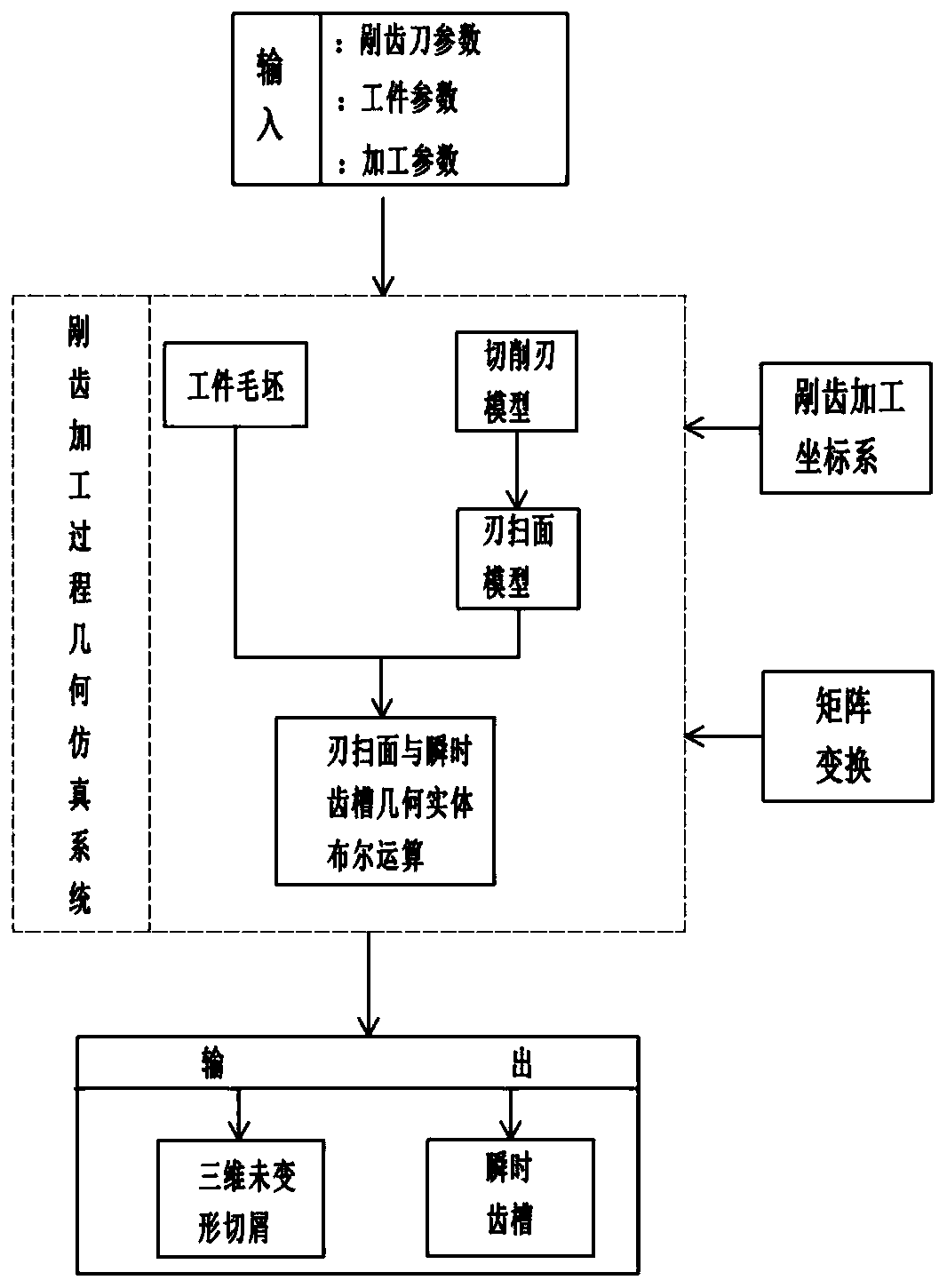
[0078] The embodiment is basically as attached figure 1 Shown: The method of building the cutting chip geometry model based on Solidworks includes parameter input, cutting edge model establishment, edge sweep surface model establishment, instantaneous cogging generation and output.

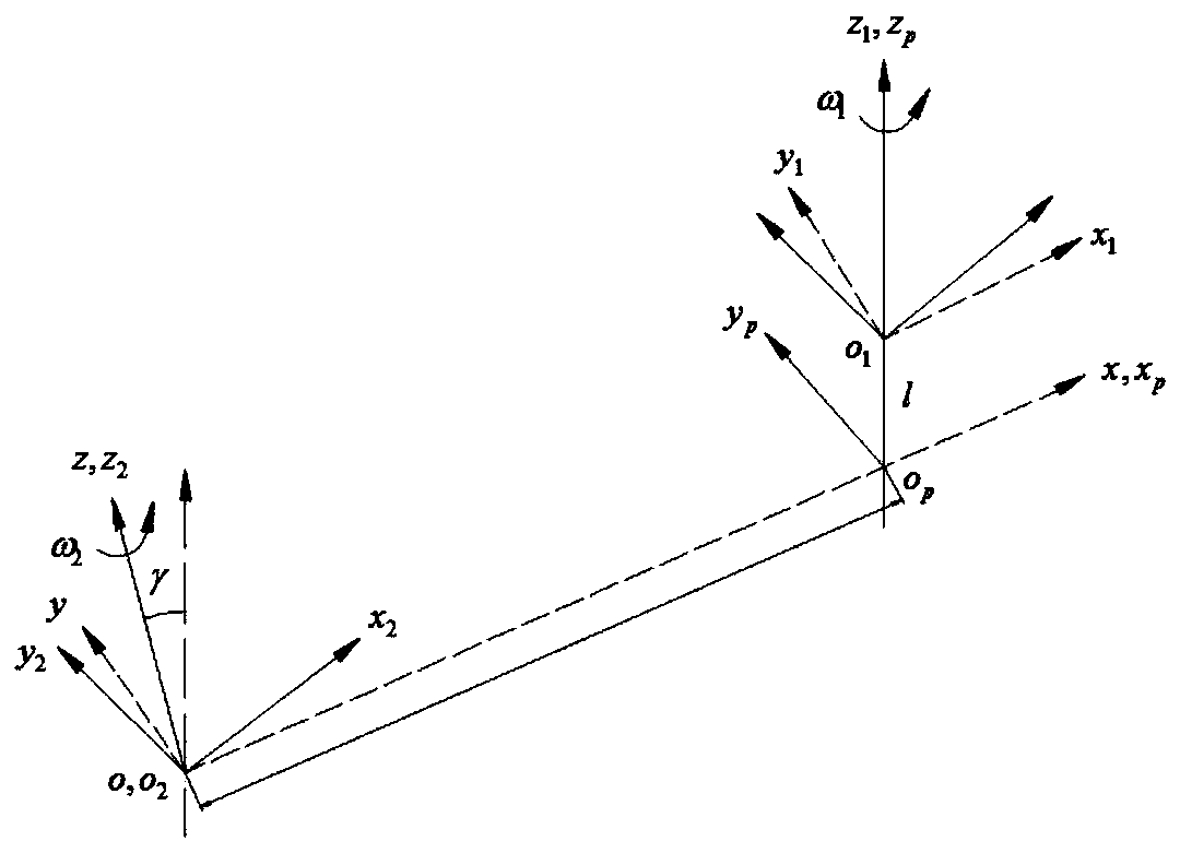
[0079] Please refer to figure 2 , where the parameters are input as follows, first establish the coordinate system: the workpiece coordinate system is S 1 (o 1 ,x 1 ,y 1 ,z 1 ), where o 1 means S 1 Coordinate origin of the coordinate system, x 1 axis, y 1 axis, z 1 The unit vectors of the axes are respectively i 1 , j 1 ,k 1 ;S p (o p ,x p , y p ,z p ) is S 1 (o 1 ,x 1 ,y 1 ,z 1 ), where o p means S p Coordinate origin of the coordinate system, x p axis, y p axis, z p The unit vectors of the axes are respectively i p , j p ,k p .

[0080] The tool coordinate system is S ...


PUM


Abstract

The invention discloses a method for constructing a cutting geometric model based on Solidworks in the field of tooth cutting machining. The effects of improving the precision of the gear and the tooth form and realizing high simulation are achieved. The technical scheme of the invention comprises the following steps of adopting a simulation system for creating a workpiece geometric entity; constructing a cutting edge model of a serrated knife; constructing an edge scanning model formed by cutting edges on teeth of a tooth cutting knife relative to a workpiece under a workpiece coordinate system; and then, combining the workpiece blank with a blade scanning surface, Boolean operation between the blade scanning surface and an instantaneous tooth groove geometric entity forms undeformed chips and new instantaneous tooth grooves, and after simulation is finished, outputting an undeformed three-dimensional chip geometric model removed in the cutting process of a certain cutter tooth of thetooth cutting cutter.

Description

technical field [0001] The invention belongs to the field of cutting gear processing, in particular to a method for constructing a geometric model of cutting chips based on Solidworks. Background technique [0002] The gear cutting technology (called Scudding or Power Skiving in foreign countries, and some domestic scholars call it gear skiving technology) is a new gear processing technology that has only been realized in the 21st century. It is difficult to process gears with special structures such as sleeves, and has the advantages of high efficiency, high precision, and dry cutting. [0003] (The following part is the research situation abroad) [0004] Since the beginning of the 21st century, German company Wera has been researching on Scudding technology without interruption. In 2006, it launched a spline rolling and inserting machine tool. In 2009, it won the bid for domestic automatic transmission parts supporting enterprises to process automatic transmission gear s...

Claims


Application Information

Patent Timeline
IPC IPC(8): G06F30/20G06F30/17
Inventor 吴晓强王利华张春友乌兰齐伟
Owner INNER MONGOLIA UNIV FOR THE NATITIES
Why Eureka
Try Eureka