A current loop delay compensation method for three-phase permanent magnet synchronous motor drive system

A permanent magnet synchronous motor, time delay compensation technology, applied in control systems, control generators, vector control systems, etc., can solve problems such as increasing hardware costs, changing hardware configuration, etc., to achieve enhanced system robustness and high observation accuracy , Dynamic response and fast effect

Active Publication Date: 2021-05-07
NANJING UNIV OF AERONAUTICS & ASTRONAUTICS
View PDF11 Cites 0 Cited by
  • Summary
  • Abstract
  • Description
  • Claims
  • Application Information

AI Technical Summary

Problems solved by technology

[0006] The technical problem to be solved by the present invention is to provide a current loop delay compensation method of a three-phase permanent magnet synchronous motor drive system for the defects involved in the background technology, so as to solve the problem that the response speed of the current loop of the permanent magnet synchronous motor drive system is affected by the digital Large delay constraints, the current tracking characteristics of traditional compensation schemes are greatly affected by changes in motor parameters, traditional current loops need to change hardware configuration or increase hardware costs and other technical problems

Method used


Image

  • A current loop delay compensation method for three-phase permanent magnet synchronous motor drive system
  • A current loop delay compensation method for three-phase permanent magnet synchronous motor drive system
  • A current loop delay compensation method for three-phase permanent magnet synchronous motor drive system

Examples


Embodiment Construction

[0057] Below in conjunction with accompanying drawing, technical scheme of the present invention is described in further detail:

[0058] This invention may be embodied in many different forms and should not be construed as limited to the embodiments set forth herein. Rather, these embodiments are provided so that this disclosure will be thorough and complete, and will fully convey the scope of the invention to those skilled in the art. In the drawings, components are exaggerated for clarity.

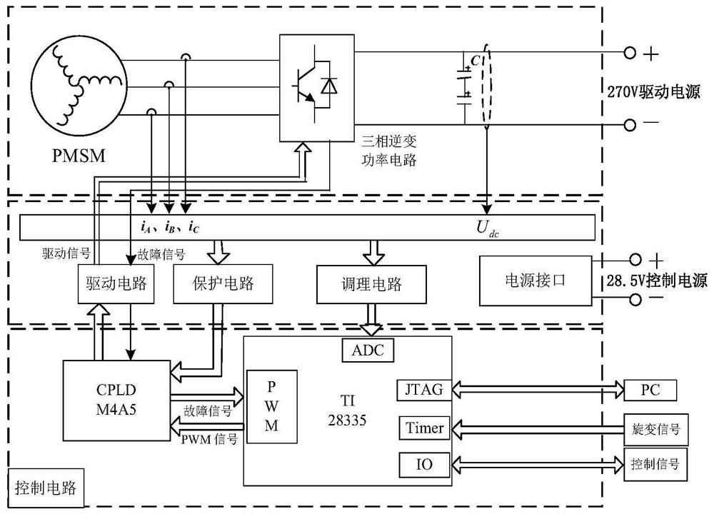
[0059] The invention discloses a current loop delay compensation method for a three-phase permanent magnet synchronous motor drive system, wherein the drive system includes a three-phase inverter power circuit, a control circuit, a bus voltage sampling circuit, a motor three-phase current sampling circuit, and a motor rotor Position sampling circuits such as figure 1 shown.

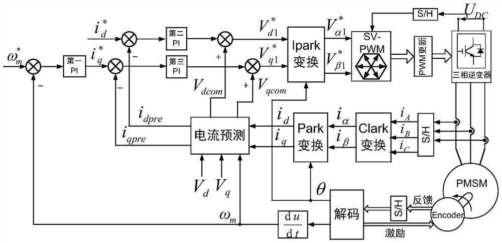
[0060] like figure 2 As shown, the delay compensation method includes the following steps:

[0061] Step 1...


PUM


Abstract

The invention discloses a current loop delay compensation method of a three-phase permanent magnet synchronous motor drive system, which predicts the next cycle based on the motor model d-q The shaft stator current is used as the feedback value of the PI regulator to calculate the reference value of the stator voltage. In view of the influence of motor parameter changes on the prediction accuracy, the present invention further corrects the above prediction model. When the actual parameters are inconsistent with the motor parameter nominal values, the error voltage item in the model will have the effect of correcting the current prediction value. The invention does not need to change the hardware configuration or add additional logic devices, has low cost, is simple to implement and is easy to expand, weakens the limitation of the digital delay on the adjustment speed of the current loop, and accelerates the current tracking characteristics, even in the case of large changes in motor parameters It still guarantees high control precision, and is suitable for permanent magnet synchronous motor drive occasions with high requirements for dynamic tracking and control precision.

Description

technical field [0001] The invention relates to the field of motor control technology, in particular to a method for compensating a current loop time delay of a three-phase permanent magnet synchronous motor drive system. Background technique [0002] Permanent magnet synchronous motor (PMSM) can achieve high precision, high dynamic performance and wide range of speed regulation, so it is used in many motor drive occasions. Rotor Field Oriented Control (FOC) is currently the most widely used motor control strategy in PMSM systems. Compared with other strategies, it has the advantage of high torque control accuracy. The rotor field oriented control adopts a cascade control structure, and the current loop is used as the inner loop of the system. Its excellent tracking characteristics and high enough bandwidth are the prerequisites to ensure the stability and fast response of the system. Without considering the d, q axis current coupling, the PMSM current loop bandwidth is rel...

Claims


Application Information

Patent Timeline
Patent Type & Authority Patents(China)
IPC IPC(8): H02P21/22H02P21/14
CPCH02P21/14H02P21/22
Inventor 朱山峰黄文新吴旭王思齐林晓刚李根
Owner NANJING UNIV OF AERONAUTICS & ASTRONAUTICS
Why Eureka
Try Eureka