Scalp clip checking machine

A technology of scalp clips and support rods, which is applied in the field of medical devices, can solve the problems of occupying the curved plate and cannot be counted, and achieve the effects of convenient counting, improved operation progress, and convenient counting

Pending Publication Date: 2020-05-05
刘恋
0 Cites 0 Cited by

AI-Extracted Technical Summary

Problems solved by technology

Existing instruments cannot be counted in a timely, accurate, intuitive and fast manner. They can only be counted one b...

Method used

After installation, the movable baffle plate is horizontally fixed on the top of the scalp clip, and the constraint scalp is clamped on the support bar, and the scalp clip is difficult for falling.
[0041] The other end of the support rod is a rotatable fixed thread, which can be fixed on the base. The base is connected with the bracket, and after the scalp clip is placed on the bracket, the movabl...

Abstract

The invention discloses a scalp clip checking machine. The scalp clip checking machine is characterized by comprising a base and four bracket rods, wherein the base is detachably connected with the bracket rods; the four bracket rods are distributed on the base in an equal distance; a movable baffle is arranged at the other end of each bracket rod, and is provided with a mounting column and a spacing baffle; a mounting slot allowing a scalp clip to place is formed in each mounting column; each spacing baffle is provided with a U-shaped accommodating groove; when each spacing baffle moves alongthe direction of the corresponding bracket rod, the corresponding mounting column is stored in the corresponding U-shaped accommodating groove; and each U-shaped accommodating groove is provided witha horizontal sliding rod adapted to the corresponding mounting slot. The scalp clip checking machine provided by the invention is compact, so that space is not occupied; and the operation progress isaccelerated and the security during the operation is also guaranteed.

Application Domain

Technology Topic

Image

  • Scalp clip checking machine
  • Scalp clip checking machine

Examples

  • Experimental program(1)

Example Embodiment

[0034] The technical solutions in the embodiments of the present invention will be clearly and completely described below with reference to the accompanying drawings in the embodiments of the present invention.
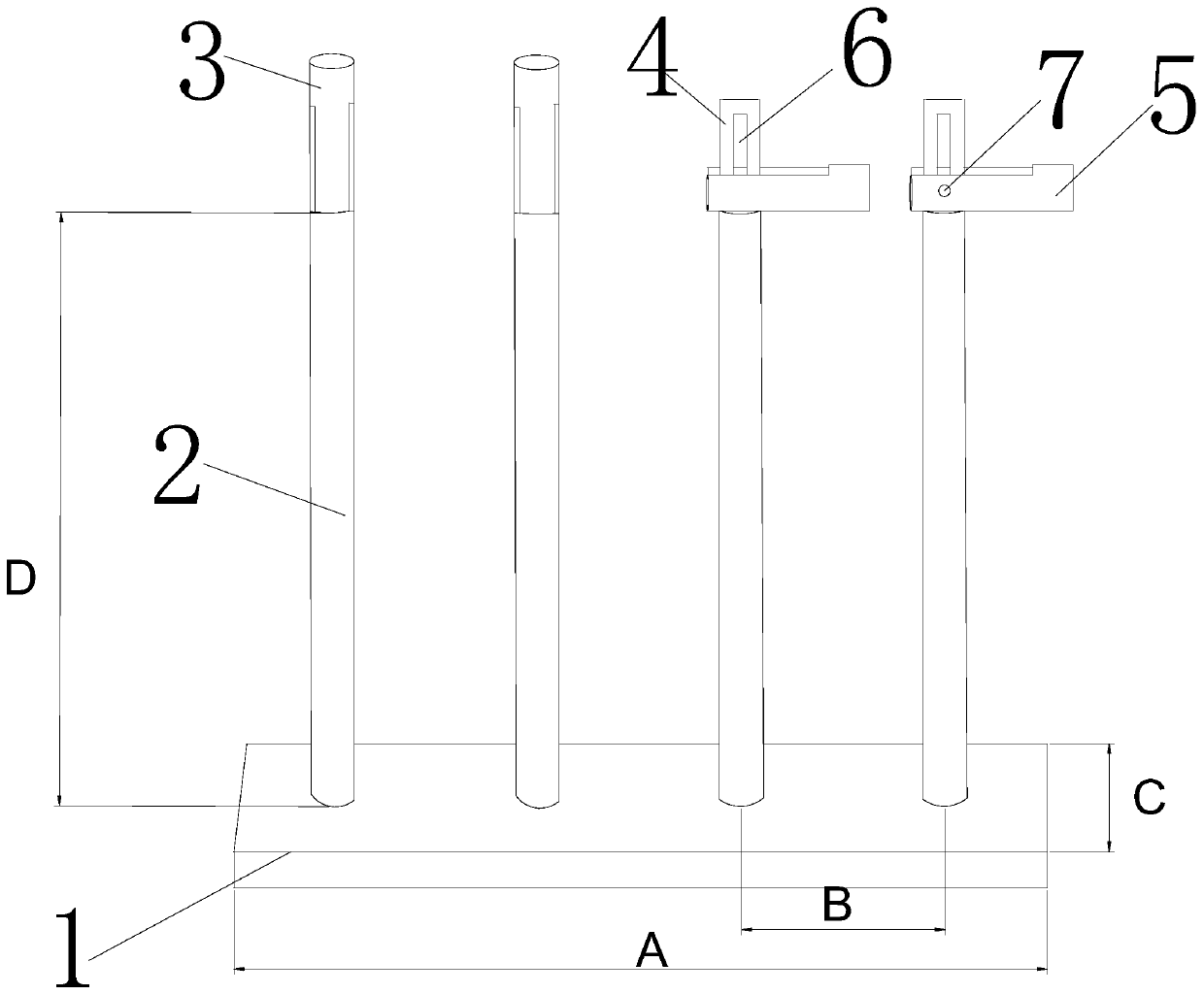
[0035] In the past, in neurosurgery, scalp clips could only be placed in curved discs or treatment bowls, and their integrity could not be timely, accurately, and directly checked. Use a curved plate or healing bowl.
[0036] After the application of the present invention, after 2 years of clinical use and continuous improvement, it has now been formed and applied to the surgical field such as brain surgery. The instrument nurses and itinerant nurses can more visualize the integrity of the scalp clip, and greatly improve the counting speed. , there is no need to scatter scalp clips in the curved plate as before, and take them one by one to check their integrity. It can not only reduce the cumbersome inventory of equipment nurses and itinerant nurses, but also avoid hidden risks during surgery. Since it was officially applied to more than 300 neurosurgery operations, it has won unanimous praise from surgeons and nurses, because it is simple and intuitive. The tedious inventorying improves work efficiency.
[0037] This innovation is also a high-quality nursing measure in my operating room, which has achieved win-win satisfaction for both the surgeon and the nurse. The results that are safe, feasible and effective will be gradually extended to the operating rooms of hospitals at all levels in our city, which has played a certain role in promoting the development of nursing in our city.
[0038] see Figure 1-Figure 2 , the present invention provides a kind of technical scheme as follows:
[0039] The scalp clip inventory device includes a base 1 and four support rods 2. The base 1 and the support rods 2 are detachably connected, specifically: the base is provided with threaded holes, and the hole distance designed in this scheme is 2.5cm, corresponding to The rod end area of ​​the bracket is set as a threaded column, and the two are connected by a thread. Four bracket rods are equally spaced on the base, the other end of the bracket is set as a movable baffle 3, and one end of the four bracket rods is a movable baffle. When in use, lift the baffle, install the scalp clip, and use After lowering the baffle, the installed scalp clip can be fixed.
[0040] The movable baffle 3 has a mounting post 4 and a limit baffle 5. The installation post is provided with a mounting slot 6 for placing the scalp clip. The limit baffle has a U-shaped accommodating groove. When the direction moves, the mounting post is accommodated in the U-shaped accommodating groove 9 , and the U-shaped accommodating groove has a transverse sliding rod 7 adapted to the mounting notch.
[0041] The other end of the bracket rod is a rotatable fixed thread, which can be fixed on the base. The base is connected to the bracket. After placing the scalp clip on the bracket, lower the movable blocking rod, which can effectively fix the scalp clip. Placing the scalp clips on the inventory device can check the integrity of the scalp clips 360 degrees without taking the scalp clips one by one, which makes the inventory more convenient and faster, and greatly improves the tediousness of the inventory.
[0042] The length A of the base 1 is 10 cm, the width C is 3 cm, and the height is 0.5 cm; the length D of the support rod is 9.5 cm, and the diameter is 0.5 cm; the length of the limit baffle is 1.5 cm. The distance B between the two bracket rods 2 is 2.5cm.
[0043] Preferably, both the base and the support rod are made of stainless steel to improve the firmness of the product.
[0044] The present invention is further described: the present invention is made up of a base and four support rods, and one end of each support rod is a movable baffle plate, and the other end is a rotatable thread, and the threaded end of the support rod is vertically fixed on the base, and the support The rods are arranged horizontally on the base. Place the scalp clips vertically and longitudinally on the support rods. Each support rod can be installed with 10 scalp clips. After installation, put down the movable baffle at the top of the support rods to fix the scalp clips on the counter.
[0045] After the scalp clips are placed in the invention, the scalp clips can be checked in an all-round way without taking them one by one, which is convenient for the instrument nurses and itinerant nurses to count them, and ensures the safety during the operation. Solve the problem of individual clinical use of scalp clip placement frame: it can only observe one side of the scalp clip, and cannot check the integrity of the scalp clip in all directions. The invention consists of a base and four support rods, the base has four circular threaded holes, and one end of the support rod with a rotatable thread is installed on the base.
[0046] The base of the invention is combined with the support rod and the movable buckle. In actual use, after the base and the support rod are installed, the movable baffle is lifted, the scalp clamp is vertically installed on the support rod, and the scalp clamp is vertically installed on the support rod, Lower the baffle to fix the scalp clip on the scalp clip counter.
[0047] After the base and the support rod are installed, the present invention is regularly and horizontally arranged on the base in an inverted T shape.
[0048] When in use, the baffle is lifted, and the baffle and the bracket rod are in a state of 180 degrees, and the scalp clip is longitudinally installed on the bracket rod, which is convenient, quick and easy to operate.
[0049] After installation, fix the movable baffle laterally on the top of the scalp clip, restrain the scalp clip on the bracket rod, and the scalp clip is not easy to fall off.
[0050] During the inventory, the instrument nurses and itinerant nurses can observe the integrity of the scalp clip from the left, right, front, back, and top in all directions, which can realize intuitive and fast inventory.
[0051] During surgery, it is easy to take when passing scalp clips.
[0052] After the operation, lift the baffle, remove the scalp clip, and rotate the four support rods counterclockwise to separate from the base.
[0053] After using the scalp clip counting device, its advantages are that it can timely, accurately and quickly count the scalp clips, save labor, low cost, can be used repeatedly, and is easy to clean, which provides a certain safety guarantee for surgical work. It can enable instrument nurses and itinerant nurses to count the number and its integrity more accurately, quickly and intuitively, avoid hidden risks and speed up the progress of surgery, so as to ensure that after the scalp clip counting device is used in surgery, its advantages are that it can be timely, accurate and fast. Inventory scalp clips.
[0054] In addition, it should be understood that although this specification is described in terms of embodiments, not each embodiment only includes an independent technical solution, and this description in the specification is only for the sake of clarity, and those skilled in the art should take the specification as a whole , the technical solutions in each embodiment can also be appropriately combined to form other implementations that can be understood by those skilled in the art.

PUM

PropertyMeasurementUnit
Length9.5cm
Diameter0.5cm
tensileMPa
Particle sizePa
strength10

Description & Claims & Application Information

We can also present the details of the Description, Claims and Application information to help users get a comprehensive understanding of the technical details of the patent, such as background art, summary of invention, brief description of drawings, description of embodiments, and other original content. On the other hand, users can also determine the specific scope of protection of the technology through the list of claims; as well as understand the changes in the life cycle of the technology with the presentation of the patent timeline. Login to view more.

Similar technology patents

Classification and recommendation of technical efficacy words

  • Easy to count
  • Simple structure

Image processing method and system

ActiveCN104751188AEasy to countEasy to classify and countCharacter and pattern recognitionSample imageImaging processing
Owner:AVE SCI & TECH CO LTD

Adjustable hand-muscle developer

InactiveCN107007973AEasy to countEasy to practiceBatteries circuit arrangementsGymnastic exercisingAcute angleEngineering
Owner:六安彩燕体育用品科技有限公司

Beam expanding optical element, beam expansion method, image display apparatus, and head-mounted display

InactiveUS20070188837A1Reduce color unevennessSimple structureOptical light guidesSubstrate with hologramHead worn displayLight wave
Owner:KONICA MINOLTA INC

Microlithographic projection exposure apparatus

InactiveUS20050068499A1Simple structureReliable and low-maintenance operationProjectorsPhotomechanical exposure apparatusCamera lensPhysics
Owner:CARL ZEISS SMT GMBH
Why Eureka
Try Eureka