Double-laser-beam deposition forming and impact forging composite additive manufacturing method

A technology of additive manufacturing and laser shock, which is applied in the field of additive manufacturing, can solve the problem of increased complexity of the cladding layer heating device, difficulty in eliminating voids, shrinkage porosity, micro-cracks in the cladding layer, and difficulty in local heating technology, etc. problems, to achieve the effect of improving internal quality and comprehensive mechanical properties, controlling macroscopic deformation and cracking, and eliminating internal defects and thermal stress

Inactive Publication Date: 2020-05-05
陈云
View PDF5 Cites 2 Cited by
  • Summary
  • Abstract
  • Description
  • Claims
  • Application Information

AI Technical Summary

Problems solved by technology

[0003] The existing pure laser cladding 3D forming process is essentially a "free additive forming" process, which generally has the following common technical problems: (1) Internal defects: process parameters, external environment, fluctuations and changes in the melt state of the molten pool, scanning The transformation of the filling track, etc., may produce various special internal metallurgical defects in the local area of ​​the part, such as pores, unfused, cracks and shrinkage internal defects, etc.
It has the following problems that affect the practicability: (1) laser shock strengthening after the cladding layer is cooled, its plastic deformation is small, it is difficult to eliminate internal defects such as voids, shrinkage porosity, and microcracks inside the cladding layer; (2) The complexity of the cladding heating device will increase exponentially with the increase in the size and structural complexity of the cladding parts, and it is even difficult to realize, and the local heating technology is even more difficult
It will take a very long time to heat a cooled 3D printed large-scale component to 700°C, and it will be very inefficient to heat up once after several layers are deposited.
(3) It is difficult for mechanical shot peening to achieve shot peening in the area, and it is very difficult to clean the shot peening
In addition, there are the following problems that affect the practicability: (1) After the SLM sintered layer forms a cross-section of the product, the product is impact-strengthened, and the plastic deformation is small, and it is difficult to eliminate the voids, shrinkage porosity, and micro-cracks inside the cladding layer. Internal defects; (2) Laser shock peening is a special term that was first proposed by the United States (Lasershock-processing, Laser peening, Laser shock-peening), and was listed as one of the key manufacturing technologies of the fourth-generation aero-engine by the United States First, the lasers currently used in engineering applications are neodymium glass lasers, YAG lasers and YLF lasers, and the laser pulse power density must exceed 10 9 W / cm 2 , but it is not yet possible to transmit such a high-pulse laser beam with an optical fiber; (3) The shock wave intensity decays with a negative exponential law inside the general metal material, and the attenuation is faster in the sintered layer with defects such as void shrinkage and porosity, and the propagation law is more Complicated, it is difficult to detect effective signals with PVDF pressure sensors. With the increase of sintered parts, the detection of laser shock wave signals becomes more and more difficult, and even the authenticity of the signals cannot be judged.

Method used


Image

  • Double-laser-beam deposition forming and impact forging composite additive manufacturing method
  • Double-laser-beam deposition forming and impact forging composite additive manufacturing method
  • Double-laser-beam deposition forming and impact forging composite additive manufacturing method

Examples


Embodiment Construction

[0020] The following will clearly and completely describe the technical solutions in the embodiments of the present invention with reference to the accompanying drawings in the embodiments of the present invention. Obviously, the described embodiments are only part of the embodiments of the present invention, not all of them. Based on the embodiments of the present invention, all other embodiments obtained by persons of ordinary skill in the art without creative efforts fall within the protection scope of the present invention.

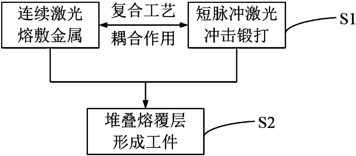
[0021] Please refer to figure 1 , figure 1 It is a step of a specific implementation mode provided by the present invention.

[0022] 1) The two laser beams work together simultaneously and with each other. The parameters include the powder feeding volume and moving speed of the first continuous laser beam, the repetition frequency, pulse width, spot diameter and angle of the second short pulse laser beam, and the distance between the two laser beams...


PUM

PropertyMeasurementUnit
melting pointaaaaaaaaaa

Abstract

The invention discloses a double-laser-beam deposition forming and impact forging composite additive manufacturing method. The method comprises the following technical characteristics that (1) two laser beams different in function simultaneously and mutually collaborate to pile up a material in a deposition zone layer by layer to form a workpiece; (2) the first beam of continuous laser conducts deposition on metal powder through the heat effect, in the meantime, the second beam of short pulse laser directly acts on the surface of deposition metal within the forging temperature range, deposition layers within the forging temperature range are subjected to impact forging through the impact wave mechanical effect of the second beam of short pulse laser. The method has the characteristics thatthe two laser beams sufficiently utilize the heat effect and the impact wave mechanical effect to simultaneously and synchronously conduct coupling operation, thus, grains of each deposition layer are refined, the strength and plasticity of the whole block-shaped material as well as the uniformity of the grain size are improved, internal defects such pores, and heat stress of the deposition layers are removed, the internal quality of metal parts and comprehensive performance of mechanics of machinery are improved remarkably, and macroscopical deformation and cracking are effectively controlled.

Description

technical field [0001] The invention relates to the technical field of additive manufacturing, in particular to a dual laser beam welding forming impact forging composite additive manufacturing method. Background technique [0002] Additive manufacturing is different from traditional "removal" manufacturing. It does not require original embryos and molds. It can directly generate objects of any shape by adding materials based on computer graphics data. It is an important development direction of advanced manufacturing technology. [0003] The existing pure laser cladding 3D forming process is essentially a "free additive forming" process, which generally has the following common technical problems: (1) Internal defects: process parameters, external environment, fluctuations and changes in the melt state of the molten pool, scanning The transformation of the filling track, etc., may produce various special internal metallurgical defects in the local area of ​​the part, such a...

Claims


Application Information

Patent Timeline
Patent Type & Authority Applications(China)
IPC IPC(8): B23K26/342B23K26/356B33Y10/00
CPCB23K26/342B23K26/356B33Y10/00
Inventor 陈云
Owner 陈云
Why Eureka
Try Eureka