Manufacturing method of glass cavity suitable for wafer-level vacuum packaging

A technology of vacuum packaging and manufacturing method, which is applied in the process of producing decorative surface effects, manufacturing microstructure devices, decorative arts, etc. The effect of lateral undercut, reduced surface undercut, and increased adhesion

Active Publication Date: 2020-05-05
BEIJING INST OF AEROSPACE CONTROL DEVICES
View PDF14 Cites 1 Cited by
  • Summary
  • Abstract
  • Description
  • Claims
  • Application Information

AI Technical Summary

Problems solved by technology

The traditional method of wet etching process is to select a single type of mask, and the back of the glass sheet cannot be well protected, resulting in serious undercutting of the glass sheet during the etching process, and it is difficult to obtain a cavity with a depth greater than 50um
If the method of DRIE is used to utilize SF 6 Gas is used for cavity etching, the etching efficiency is low and the depth cannot be precisely controlled
There is also a method of using silicon dry etching and softening the glass after anodic bonding to make a glass deep cavity. Although this method can obtain a pattern with an aspect ratio of 20:1, when the depth exceeds 100 μm, the deviation in the chip is large. , and the production efficiency is low
The getter thin film material is formed inside the cavity, and it is difficult to realize the internal patterning of the cavity with a depth of more than 50 μm by the conventional photolithography process

Method used


Image

  • Manufacturing method of glass cavity suitable for wafer-level vacuum packaging
  • Manufacturing method of glass cavity suitable for wafer-level vacuum packaging
  • Manufacturing method of glass cavity suitable for wafer-level vacuum packaging

Examples


Embodiment Construction

[0037] The present invention will be further elaborated below in conjunction with embodiment.

[0038] In the first step, the TEMPAX glass sheet is successively treated with H at 110-130°C and a volume ratio of 4:1 2 SO 4 and H 2 o 2 The mixed solution, 75-85 ℃, NH with a volume ratio of 1:1:5 4 OH, H 2 o 2 and H 2 Mixture of O, 75-85°C, HCl, H with a volume ratio of 1:1:6 2 o 2 and H 2 The mixture of O was cleaned.

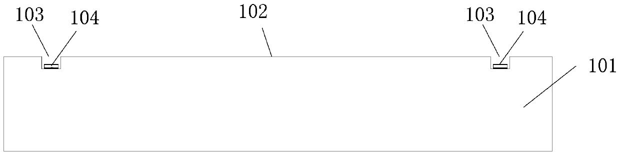
[0039] The second step is to use photolithography to make patterns on the glass surface, and use room temperature BOE solution to etch shallow grooves with a depth of 0.2 μm on the glass surface to remove the photoresist.

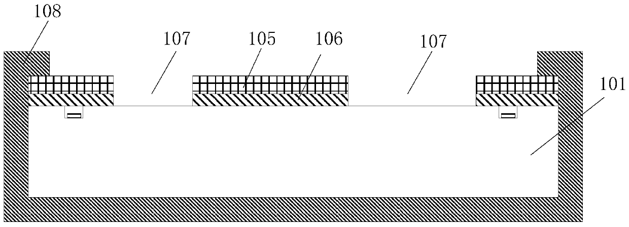
[0040] In the third step, the glass sheets are successively exposed to H with a volume ratio of 4:1 at 110-130°C. 2 SO 4 and H 2 o 2 The mixed solution, 75-85 ℃, NH with a volume ratio of 1:1:5 4 OH, H 2 o 2 and H 2 Mixture of O, 75-85°C, HCl, H with a volume ratio of 1:1:6 2 o 2 and H 2 The mixed solution of O was cleaned...


PUM

PropertyMeasurementUnit
depthaaaaaaaaaa
thicknessaaaaaaaaaa
thicknessaaaaaaaaaa

Abstract

The invention relates to a manufacturing method of a glass cavity suitable for wafer-level vacuum packaging. The manufacturing method comprises the following steps: carrying out primary cleaning on aglass sheet; etching the surface of the glass to form a first pattern; carrying out secondary cleaning on the glass sheet; depositing a metal tungsten film on the surface of the glass; forming a second pattern on the tungsten film in the shallow groove formed by the first pattern in the second step; depositing a composite gold film on the surface of the glass; the composite gold film is coated with photoresist, photoetching is conducted on the gold film, and a cavity pattern is formed; protecting the edges of the gold-film-free surface and the gold-film-containing surface of the glass sheet byusing a blue film; and aligning the silicon wafer with the hollow pattern with the glass sheet with the glass sheet cavity according to the second pattern to form the glass sheet with the getter filmin the cavity for wafer-level vacuum packaging. The thick photoresist and the metal film are adopted to form the composite mask, the influence of defects and pinholes on the surface of the single-layer mask on corrosion can be eliminated, and surface undercutting in the glass corrosion process is reduced.

Description

technical field [0001] The invention belongs to the technical field of micromechanical and electronic MEMS manufacturing, and relates to a method for manufacturing a glass cavity suitable for wafer-level vacuum packaging. Background technique [0002] In the field of MEMS packaging, since MEMS devices generally have movable parts, it is necessary to use a cavity structure to seal and protect the device during packaging, so that the movable parts have a movable space and play a physical role in protecting the device. Some MEMS devices Such as resonators, gyroscopes, etc. also require a vacuum-tight packaging environment. The silicon-glass anodic bonding process can provide very good airtightness and is a common bonding process for wafer-level vacuum packaging. A deep cavity structure is formed on the bonded glass sheet, and a getter film for absorbing excess gas is made on the surface of the cavity, so that the bonded glass sheet can be anodically bonded to the silicon subst...

Claims


Application Information

Patent Timeline
Patent Type & Authority Applications(China)
IPC IPC(8): B81C1/00
CPCB81C1/00261B81C1/00285
Inventor 杨静刘福民张树伟张乐民徐宇新刘国文
Owner BEIJING INST OF AEROSPACE CONTROL DEVICES
Why Eureka
Try Eureka