Assembly-type deep and large round vertical shaft structure for rock stratum area and construction method

A prefabricated, construction method technology, applied in vertical shaft equipment, well sinking, wellbore lining, etc., can solve the problems of high risk, high investment, low work efficiency, etc.

Active Publication Date: 2020-05-05
JIESHUN RAIL TRAFFIC TECH CHONGQING
View PDF5 Cites 2 Cited by
  • Summary
  • Abstract
  • Description
  • Claims
  • Application Information

AI Technical Summary

Problems solved by technology

For deep and large shafts, the traditional shaft construction method has low work efficiency, high risk, strong initial support and high investment

Method used


Image

  • Assembly-type deep and large round vertical shaft structure for rock stratum area and construction method
  • Assembly-type deep and large round vertical shaft structure for rock stratum area and construction method
  • Assembly-type deep and large round vertical shaft structure for rock stratum area and construction method

Examples


Embodiment 1

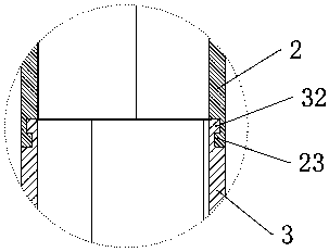
[0040] Example 1, please refer to Figure 1-6 , the present invention solves the above-mentioned technical problems through the following technical means: the present invention provides an assembled deep and large circular shaft structure in a rock formation area, including a locking ring beam 1 arranged at the wellhead of the circular shaft, and the locking ring beam 1 The lower end is provided with a first annular segment 2, and the first shaft segment includes multiple pieces, and the plurality of first annular segments 2 surround a circular first section shaft 21, and the first annular segment 2 Connected by bolts in the ring direction, the lower end of the first annular segment 2 is connected with the second annular segment 3, and a plurality of the second annular segment 3 surrounds the second shaft 31, and the first shaft 21 The lower connection has multiple second section shafts 31, which are arranged sequentially from top to bottom. The inner ring of the locking ring ...

Embodiment 2

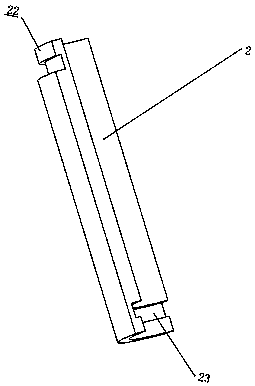
[0045] Example 2, please refer to Figure 7-11 , the joint part 11 is an "L"-shaped protrusion arranged on the inner ring of the locking ring beam, the first upper interface 22 is an "L"-shaped notch matching the joint part 11, and the first upper The interface 22 is arranged on the outer wall of the upper end of the first annular pipe, and is recessed from the outer wall of the first annular pipe to its inside. "L"-shaped notch, the first lower interface 23 is arranged on the inner wall of the lower end of the first annular tube, and is recessed from the inner wall of the first annular tube toward the outer wall, and the second annular segment 3 is connected to the first annular tube Segment 2 has exactly the same structure. The joint part 11 with the "L"-shaped protrusion and the "L"-shaped notch is connected with the first upper interface 22, so that the connection is convenient and fast, and the first annular segment 2 is directly hooked to the locking ring beam 1 Just p...


PUM


Abstract

The invention provides an assembly-type deep and large round vertical shaft structure for a rock stratum area. The assembly-type deep and large round vertical shaft structure comprises fore shaft ringbeams arranged at the shaft mouth of a round vertical shaft, wherein the lower end of each fore shaft ring beam is provided with a first annular duct piece, a plurality of second vertical shaft sections are connected to the lower portion of the first vertical shaft section and are arranged in sequence from top to bottom, an inner ring of each fore shaft ring beam is provided with a joint part, and the first annular duct pieces are hung on the fore shaft ring beams through first upper connectors and joint parts. The round vertical shaft is a structure formed by assembling a plurality of annular duct pieces, the fore shaft ring beams are utilized for bearing, the joint parts, the first upper connectors, first lower connectors, second upper connectors and first lower connectors are adopted for connection, digging and assembly can be conducted simultaneously, the construction efficiency is effectively improved, preliminary bracing is reduced, the project period and project investment aresaved, and environmental pollution and construction risks brought by cast-in-situ concrete construction are avoided.

Description

technical field [0001] The invention relates to the technical field of construction engineering, in particular to a prefabricated deep and large circular shaft structure in a rock formation area and a construction method. Background technique [0002] The traditional circular shaft structure in the rock stratum is usually constructed by cast-in-place method. The shaft is excavated while doing the primary support, and the shaft is excavated to the bottom. For deep and large shafts, the traditional shaft construction method has low work efficiency, high risk, strong initial support and high investment. Contents of the invention [0003] In view of this, the problem to be solved by the present invention is to provide an assembled deep circular shaft structure and construction method in the rock formation area. Using this structure and construction method can effectively improve construction efficiency, reduce initial support, and save construction period and construction meth...

Claims


Application Information

Patent Timeline
Patent Type & Authority Applications(China)
IPC IPC(8): E21D1/08E21D5/04
CPCE21D1/08E21D5/04
Inventor 周捷邹光炯彭辉易谊孙伟梅乐胜吴焕君陈波宋何阳杨帆
Owner JIESHUN RAIL TRAFFIC TECH CHONGQING
Why Eureka
Try Eureka