
Integrated six-dimensional force sensor with double-I-shaped cross beam structure

A technology of six-dimensional force sensor and shaped cross beam, which is applied in the direction of measuring force components, etc., can solve the problems of difficult to apply to the end of the robot actuator, low sensitivity, and small gap between the serpentine structure beams, so as to improve the anti-overload performance and use The effect of safety, high measurement sensitivity and low processing difficulty

Active Publication Date: 2020-05-05
SHANGHAI JIAO TONG UNIV
View PDF10 Cites 4 Cited by
  • Summary
  • Abstract
  • Description
  • Claims
  • Application Information

AI Technical Summary

Problems solved by technology

However, when the overall size of the force sensor is small, the gap between the beams of the serpentine structure is small, which is difficult to manufacture
[0007] The application number is CN201910524444. The Chinese patent provides a six-dimensional force sensor applied to industrial sites. It adopts the traditional cross-beam junction design and sets a limit structure. It has a certain overload capacity, but the cross-beam stiffness is relatively large and the sensor sensitivity is high. Low, difficult to apply to the end of the robot actuator
[0008] Although the above-mentioned patents provide an innovative force sensor design, the current six-dimensional force sensor still has complex structures, weak overload resistance, low sensitivity, and Complicated installation and other issues

Method used


Image

  • Integrated six-dimensional force sensor with double-I-shaped cross beam structure
  • Integrated six-dimensional force sensor with double-I-shaped cross beam structure
  • Integrated six-dimensional force sensor with double-I-shaped cross beam structure

Examples


Embodiment Construction

[0052] The present invention will be described in detail below in conjunction with specific embodiments. The following examples will help those skilled in the art to further understand the present invention, but do not limit the present invention in any form. It should be pointed out that for those of ordinary skill in the art, a number of modifications and improvements can be made without departing from the concept of the present invention. These all belong to the protection scope of the present invention.

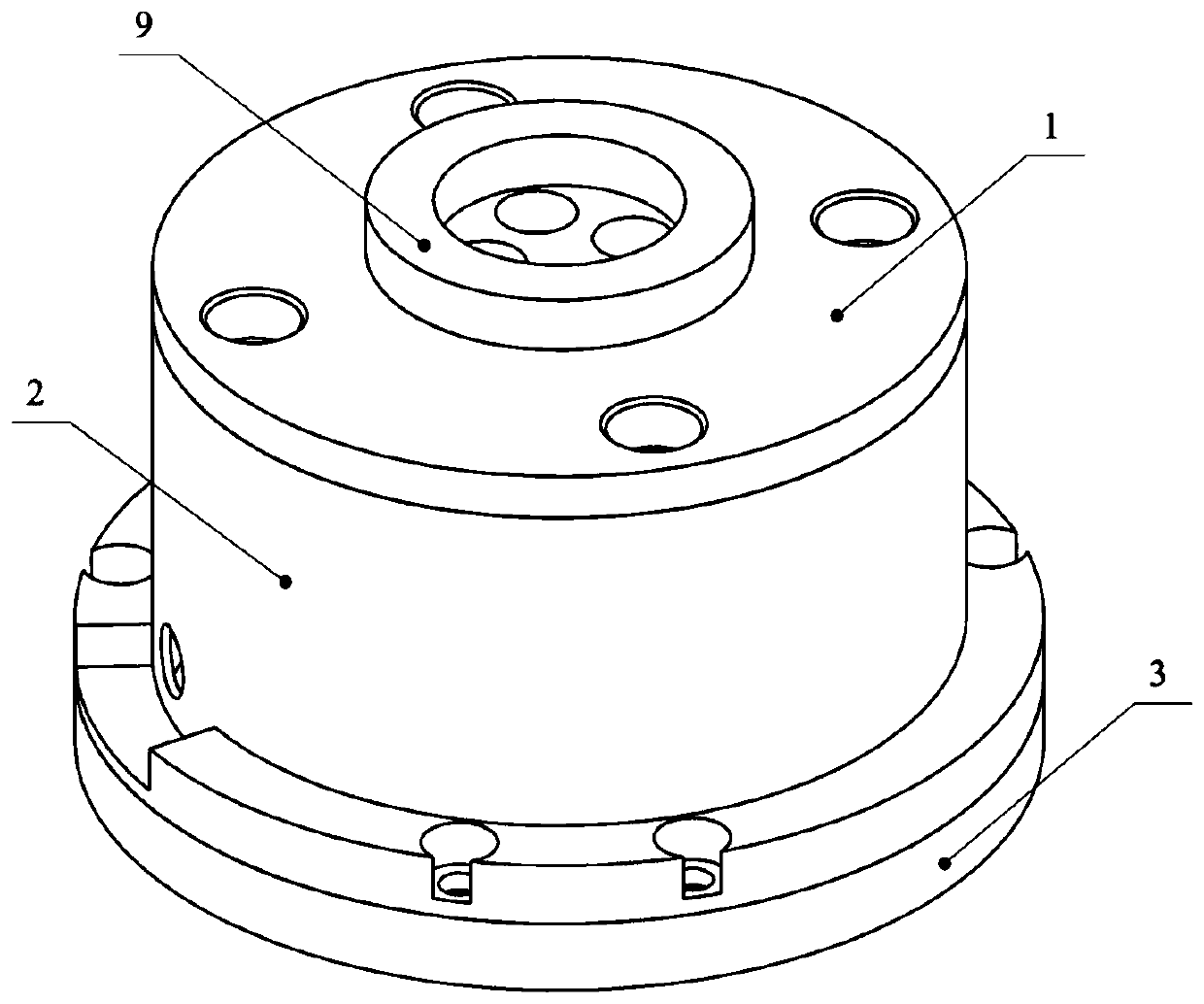
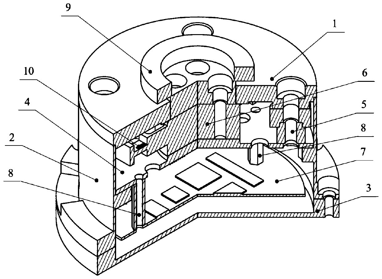
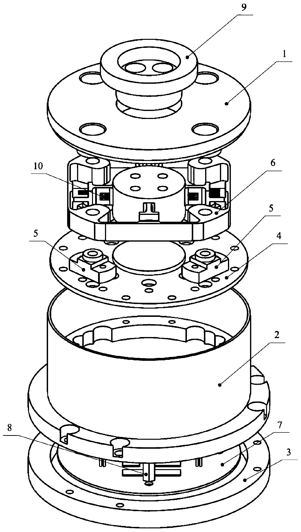
[0053] Reference figure 1 , figure 2 , image 3 As shown, it is a structural schematic diagram of an integrated six-dimensional force sensor with a double "I"-shaped cross beam structure in an embodiment of the present invention.

[0054] Reference figure 1 As shown, the sensor includes: a double "I" shaped cross beam 6 and a number of resistance strain gauges 10; among them, the double "I" shaped cross beam 6 includes an outer ring 6-1, four elastic bodies 6-2A, 6- 2B, 6-2...


PUM


Abstract

The invention provides an integrated six-dimensional force sensor with a double-I-shaped cross beam structure. The integrated six-dimensional force sensor comprises a double-I-shaped cross beam and aplurality of resistance strain gauges. The double-I-shaped cross beam comprises an outer ring, four elastic bodies and an inner ring. The four elastic bodies are uniformly distributed between the outer ring and the inner ring in a spoke form, and the four elastic bodies are symmetrically distributed in a cross shape to form a cross beam which is used for sensing stress; each elastic body comprisesa first I-shaped component and a second I-shaped component which are perpendicular to each other so that cross beams of the first I-shaped component and the second I-shaped component respectively form a horizontal plate and a vertical plate which are perpendicular to each other; and a plurality of resistance strain gauges are respectively arranged on the upper and lower surfaces of the horizontalplate and the two side surfaces of the vertical plate. The sensor has the advantages of simple structure, convenience in processing, small inter-dimensional coupling, high sensitivity, high overloadresistance and the like, the mechanical structure of the sensor and the signal control circuit are integrated for integrated design, and the sensor can be flexibly and conveniently integrated at the tail end of a robot actuating mechanism.

Description

Technical field [0001] The invention belongs to the application field of robots and their sensors, and relates to a force sensor, in particular to an integrated six-dimensional force sensor with a double "I" shaped cross beam structure. Background technique [0002] With the continuous development of robot technology, the demand for force control at the end of the robot actuator is also increasing. The six-dimensional force sensor can detect the size of the three-dimensional force and moment in space, which can meet the force control requirements of the end of the robot actuator. The existing six-dimensional force sensor is relatively mature, but in the field of robotics, especially for the force control requirements of the end of the robot actuator, the performance of the six-dimensional force sensor has higher requirements, such as small size, high sensitivity, High security. [0003] After searching the literature of the prior art, it is found that the Chinese patent with appl...

Claims


Application Information

Patent Timeline
IPC IPC(8): G01L5/16
CPCG01L5/16
Inventor 付庄王科瑾冯新付泽宇赵艳娜谢荣理张俊费健
Owner SHANGHAI JIAO TONG UNIV
Learn More