Carrier and device

a carrier and carrier technology, applied in the field of carriers and devices, can solve the problems of difficult to achieve good performance in the 850 and 900 mhz gsm bands, low band bandwidth, etc., and achieve the effects of improving the high band bandwidth, high impedance, and high bandwidth

Inactive Publication Date: 2010-01-05
SONY CORP
View PDF11 Cites 4 Cited by
  • Summary
  • Abstract
  • Description
  • Claims
  • Application Information

AI Technical Summary

Benefits of technology

[0011]This antenna pattern described above constitutes part of a high gain multi-band branched monopole or semi-PIFA antenna with good talking performance. The position of the wider branch and the narrower branch relative to one another namely result in an antenna having good directivity in the high bands (such as 1710-2170 MHz), such as DCS, PCS and UMTS band 1, 2, which results in lower emissions towards a user's head in high-bands, where the directivity of an antenna measures the power density an antenna radiates in the direction of its strongest emission, relative to the power density radiated by an ideal isotropic radiator antenna radiating the same amount of total power. A front to back ratio of at least 1 dB can consequently be obtained.
[0012]Furthermore, the antenna is ground free so it functions as a monopole antenna in the low bands (such as 824-960 MHz) and significant bandwidth can be achieved even if the antenna occupies a small volume. The antenna is easy to tune to a desired frequency band and it is simple and inexpensive to manufacture. The antenna also provides good isolation between the narrower branch and the wider branch (i.e. there is very little capacitive coupling between the narrower branch and the wider branch).
[0023]The narrower branch may have a total length (as measured along the narrower branch from the feed point via the common point to a distal end of the narrower branch) that is at least about 30% longer than the total length of the wider branch (as measured along the wider branch from the common point to a distal end of the wider branch), preferably at least about 40% longer and more preferably at least about 50% longer. The longer narrower branch constitutes a high impedance area which serves to improve the bandwidth of the high band.

Problems solved by technology

A further challenge facing manufacturers is to provide electronic devices with a compact, high gain, multi-band antenna i.e. an antenna capable of simultaneously transmitting and / or receiving signals using different wireless communication standards, such as GPS, Rx diversity, W-LAN, Wi-Fi, Bluetooth and UWB, with a good front to back ratio.
It is however also well known that PIFA antennas have narrow low-band bandwidth and that it is difficult to achieve good performance in the 850 and 900 MHz GSM bands if the antenna occupies small volume.

Method used


Image

  • Carrier and device
  • Carrier and device
  • Carrier and device

Examples


Embodiment Construction

[0035]The following detailed description refers to the accompanying drawings. The detailed description does not limit the invention. Instead, the scope of the invention is defined by the appended claims and equivalents.

[0036]The term “about” is used herein to mean approximately, roughly, around, or in the region of. When the term “about” is used in conjunction with a numerical range, it modifies that range by extending the boundaries above and below the numerical values set forth. In general, the term “about” is used herein to modify a numerical value above and below the stated value by a variance of 10 percent up or down (higher or lower).

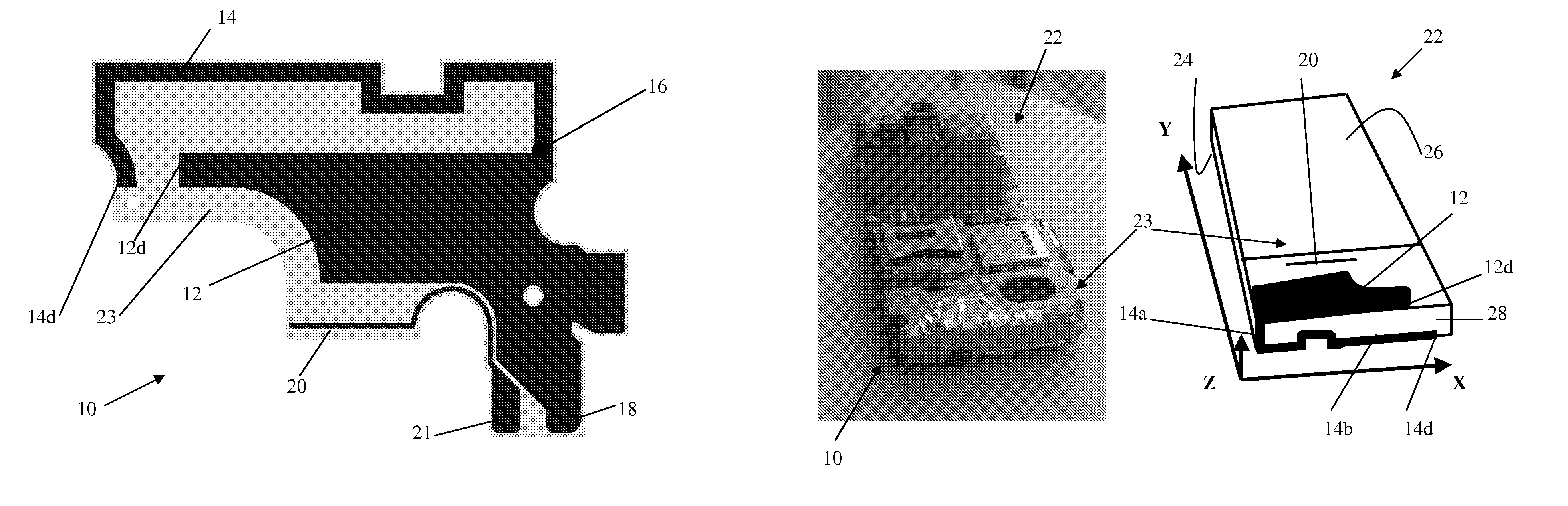
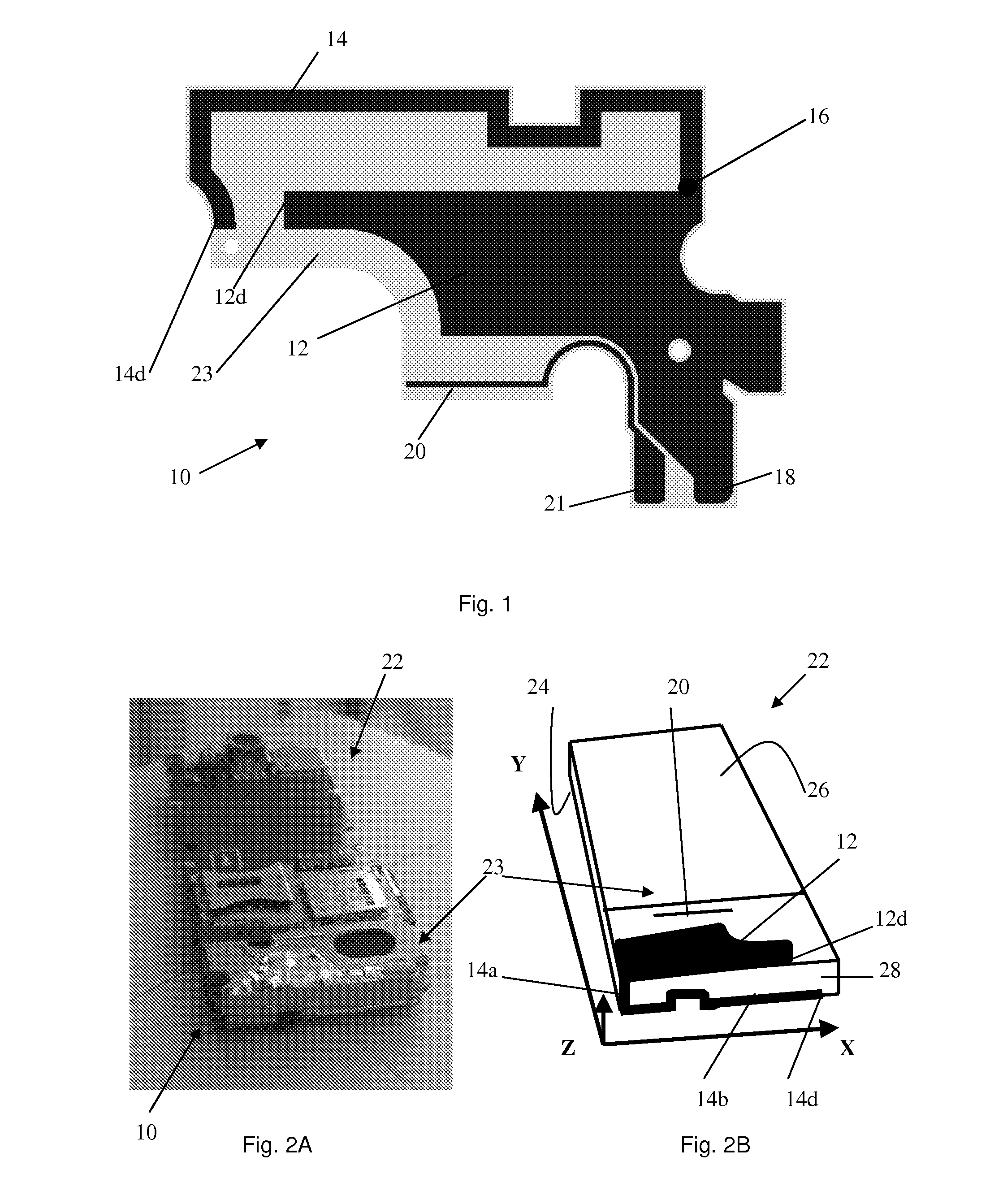
[0037]FIG. 1 shows a flat antenna pattern 10 (represented by the darker color in FIG. 1) according to an embodiment of the invention. The antenna pattern 10 comprises a shorter wider branch 12 and a longer narrower branch 14. The shorter wider branch 12 and the longer narrower branch 14 extend from a common point 16. The antenna pattern 10 compris...


PUM


Abstract

A carrier that extends in three mutually orthogonal directions, X, Y and Z, when in use and which comprises a back surface defining a first XY-plane and a side surface defining an XZ-plane, whereby the carrier comprises an antenna pattern. The antenna pattern comprises a wider branch that is located on the back surface of the carrier, and a narrower branch that comprises a first section that extends substantially along the Z-direction of the side surface and a second section that extends substantially in the X-direction of the side surface.

Description

FIELD OF THE INVENTION[0001]The present invention relates to a carrier comprising an antenna pattern and a device comprising such a carrier.BACKGROUND OF THE INVENTION[0002]An antenna is a transducer designed to transmit and / or receive radio, television, microwave, telephone and radar signals, i.e. an antenna converts electrical currents of a particular frequency into electromagnetic waves and vice versa. Physically, an antenna is an arrangement of one or more electrical conductors that is arranged to generate a radiating electromagnetic field in response to an applied alternating voltage and the associated alternating electric current, or that can be placed in an electromagnetic field so that the field will induce an alternating current in the antenna and a voltage between its terminals.[0003]Portable wireless communication electronic devices, such as mobile phones, typically include an antenna that is connected to electrically conducting tracks or contacts on a printed circuit boa...

Claims


Application Information

Patent Timeline
Patent Type & Authority Patents(United States)
IPC IPC(8): H01Q1/38H01Q5/371H01Q5/378
CPCH01Q1/243H01Q5/378H01Q5/371H01Q1/38
Inventor VANCE, SCOTT
Owner SONY CORP
Why Eureka
Try Eureka