Antenna sharing device

a technology of an antenna and a ring, which is applied in the direction of piezoelectric/electrostrictive/magnetostrictive devices, electrical apparatus, impedence networks, etc., can solve the problems of increasing the steepness of attenuation characteristics in frequencies higher than the passband, increasing the steepness of attenuation characteristics in frequencies lower than the passband, and increasing the loss in the receiving passband. , to achieve the effect of increasing the steepness of atten

Active Publication Date: 2012-03-15
SKYWORKS PANASONIC FILTER SOLUTIONS JAPAN
View PDF6 Cites 5 Cited by
  • Summary
  • Abstract
  • Description
  • Claims
  • Application Information

AI Technical Summary

Benefits of technology

[0012]Such structured first elastic wave filter allows the first series resonator to have an electromechanical coupling factor smaller than that of the second series resonator. The first series resonator has an antiresonant frequency lower than that of the second series resonator, which largely contributes to steepened attenuation characteristics on the high-frequency side of the first elastic wave filter. Therefore, determining the electromechanical coupling factor of the first series resonator to be relatively small increases steepness in attenuation characteristics in a crossband (on the high-frequency side of the first elastic wave filter). On the other hand, the second series resonator has an antiresonant frequency higher than that of the first series resonator, which largely contributes to low loss in the passband of the first elastic wave filter. Therefore, determining the electromechanical coupling factor of the second series resonator to be relatively large achieves low loss in the passband.
[0014]Such structured second elastic wave filter allows the first parallel resonator to have an electromechanical coupling factor smaller than that of the second parallel resonator. The first parallel resonator has an antiresonant frequency higher than that of the second parallel resonator, which largely contributes to steepened attenuation characteristics on the low-frequency side of the second elastic wave filter. Therefore, determining the electromechanical coupling factor of the first parallel resonator to be relatively small increases steepness in attenuation characteristics in a crossband (on the low-frequency side of the second elastic wave filter). On the other hand, the second parallel resonator has an antiresonant frequency lower than that of the first parallel resonator, which largely contributes to low loss in the passband of the second elastic wave filter. Therefore, determining the electromechanical coupling factor of the second parallel resonator to be relatively large achieves low loss in the passband.

Problems solved by technology

According to the conventional antenna sharing device, however, increase in steepness in attenuation characteristics has brought the following problems.
In the transmit filter, increasing the steepness in attenuation characteristics in frequencies higher than the passband increases loss in the transmitting passband.
Similarly, in the receive filter, increasing the steepness in attenuation characteristics in frequencies lower than the passband increases loss in the receiving passband.
As described above, the pending problem of the conventional antenna sharing device is to satisfy both of properly steep attenuation characteristics in a crossband and low loss in a passband.

Method used


Image

  • Antenna sharing device
  • Antenna sharing device
  • Antenna sharing device

Examples


first exemplary embodiment

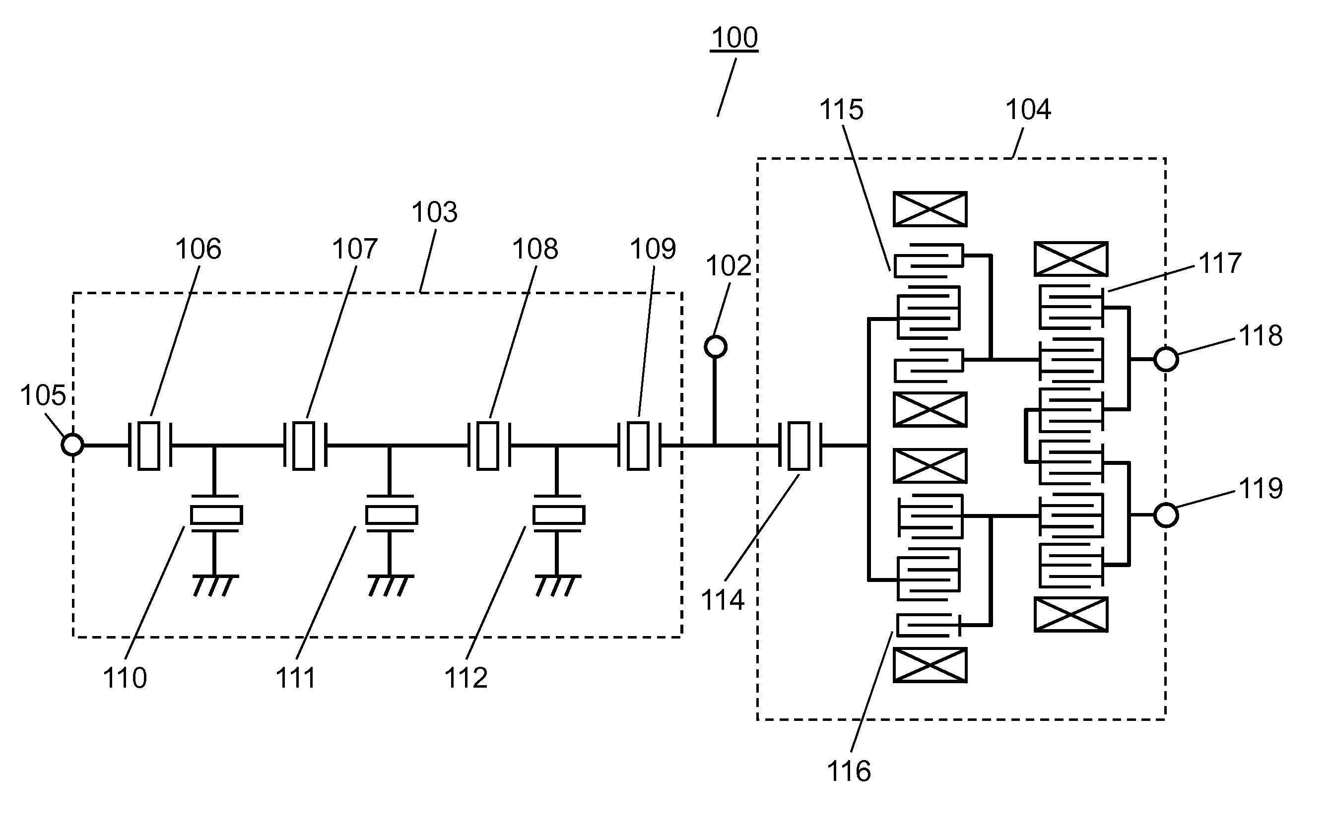
[0025]FIG. 1 is a schematic circuit diagram of the antenna sharing device in accordance with the first exemplary embodiment. Specifically, the antenna sharing device is compliant with Band 2 of the W-CDMA (Wideband Code Division Multiple Access) standard.

[0026]Antenna sharing device 100 of FIG. 1 has first elastic wave filter 103 as a transmit filter and second elastic wave filter 104 as a receive filter, both of which are connected to antenna terminal 102.

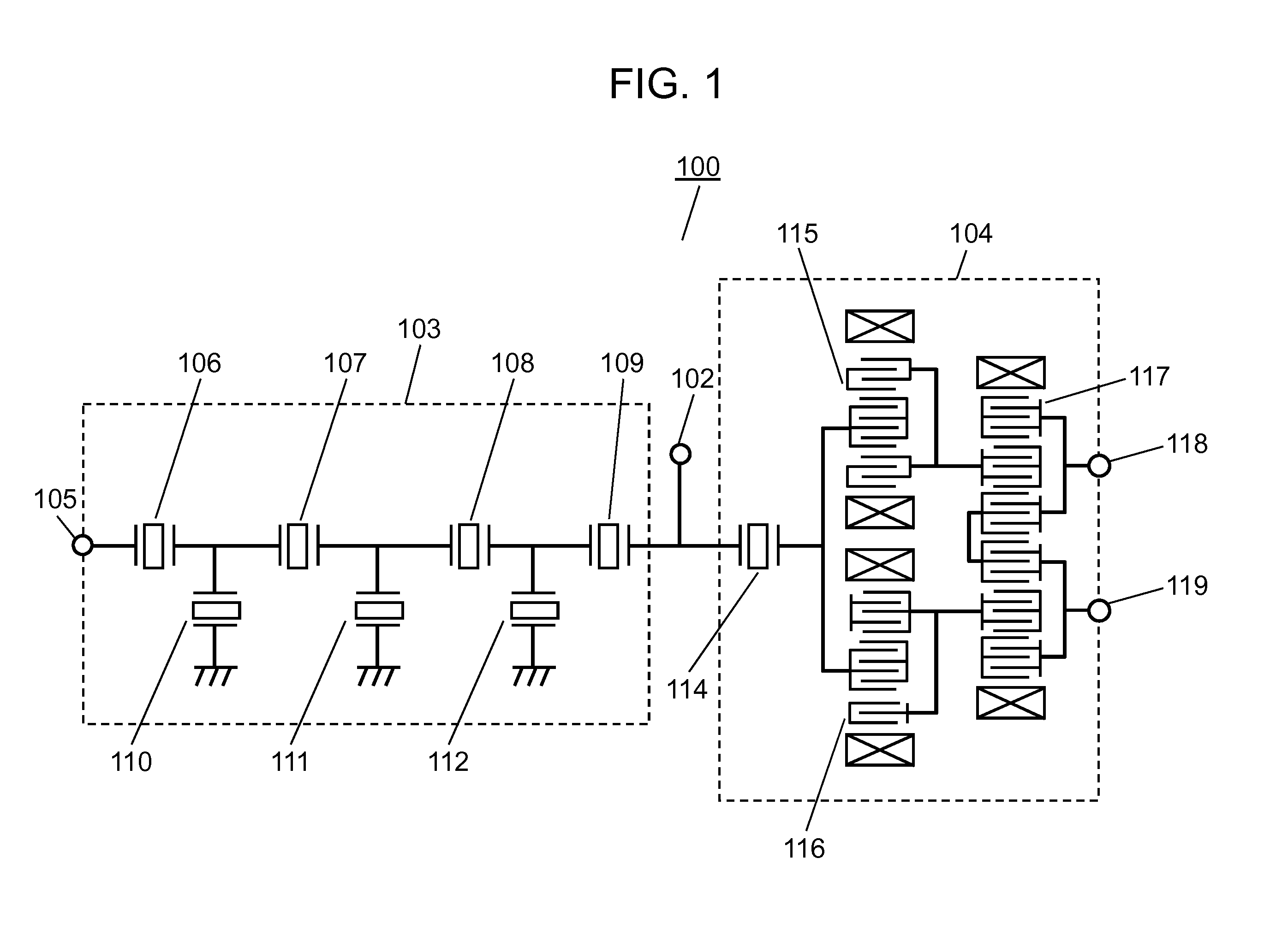
[0027]In Band-2 antenna sharing device 100, for example, first elastic wave filter 103 allows passage of signals in a transmitting band of 1.85 GHz-1.91 GHz (hereinafter, a first frequency band). Second elastic wave filter 104 allows passage of signals in a receiving band of 1.93 GHz-1.99 GHz (hereinafter, a second frequency band) that is higher than the first frequency band.

[0028]Hereinafter, first elastic wave filter 103 and second elastic wave filter 104 will be described in detail.

[0029]First elastic wave filter 103 is a ladde...

second exemplary embodiment

[0058]The structure of the second exemplary embodiment will be described. The description below focuses attention on differences from the structure in the first embodiment.

[0059]FIG. 8 is a schematic circuit diagram of the antenna sharing device in accordance with the second exemplary embodiment.

[0060]Antenna sharing device 200 of FIG. 8 has first elastic wave filter 103 as a ladder type transmit filter and second elastic wave filter 201 as a ladder type receive filter.

[0061]Second elastic wave filter 201 has series resonator 202, series resonator 203, series resonator 204, and series resonator 205, which are connected in series between antenna terminal 102 and receive terminal 209. Second elastic wave filter 201 further contains parallel resonator 206, parallel resonator 207, and parallel resonator 208. Parallel resonator 206 is disposed between series resonator 202 and series resonator 203 so as to be connected to ground in parallel. Parallel resonator 207 is disposed between seri...


PUM


Abstract

The antenna sharing device has a first elastic-wave filter for passing signals of a first frequency passband and a second elastic-wave filter for passing signals of a second frequency passband higher than the first frequency passband. The first elastic-wave filter is a ladder-type filter including a first series resonator and a second series resonator having an antiresonant frequency point higher than that of the first series resonator. The first series resonator has a first IDT electrode and a first dielectric film covering the electrode. The second series resonator has a second IDT electrode and a second dielectric film covering the electrode. The first and the second dielectric films have a first projection and a second projection, respectively, so as to be formed above the electrode fingers of each IDT electrode. The cross-sectional area of the first projection of the first series resonator is larger than that of the second projection of the second series resonator in the excitation direction of the elastic wave. The structure satisfies both of steepness in a crossband and low loss in a passband.

Description

[0001]THIS APPLICATION IS A U.S. NATIONAL PHASE APPLICATION OF PCT INTERNATIONAL APPLICATION PCT / JP2010 / 003154.TECHNICAL FIELD[0002]The present invention relates to an antenna sharing device having a transmit filter and a receive filter.BACKGROUND ART[0003]An antenna sharing device generally has two types of filters—a transmit filter and a receive filter—for separating signals of the transmitting passband from signals of the receiving passband that is adjacent to the higher side of the transmitting passband. The transmit filter is generally formed of a ladder type filter where series resonators and parallel resonators are connected in a ladder structure.[0004]In Band 2 of the W-CDMA standard, the band spacing between the transmitting passband and the receiving passband (i.e. the crossband) is determined to be 20 MHz. In an antenna sharing device that copes with such a narrow crossband above, steepness in attenuation characteristics in the crossband between the transmitting passband ...

Claims


Application Information

Patent Timeline
Patent Type & Authority Applications(United States)
IPC IPC(8): H03H9/70
CPCH03H9/725H03H9/0071
Inventor TSURUNARI, TETSUYAGOTO, REINAKAMURA, HIROYUKI
Owner SKYWORKS PANASONIC FILTER SOLUTIONS JAPAN
Why Eureka
Try Eureka