
Optical signal collecting device and etching equipment

A technology for collecting devices and optical signals, which is applied to discharge tubes, electrical components, circuits, etc., and can solve the problems of many steps and long time.

Active Publication Date: 2020-05-05
BEIJING NAURA MICROELECTRONICS EQUIP CO LTD
View PDF4 Cites 1 Cited by
  • Summary
  • Abstract
  • Description
  • Claims
  • Application Information

AI Technical Summary

Problems solved by technology

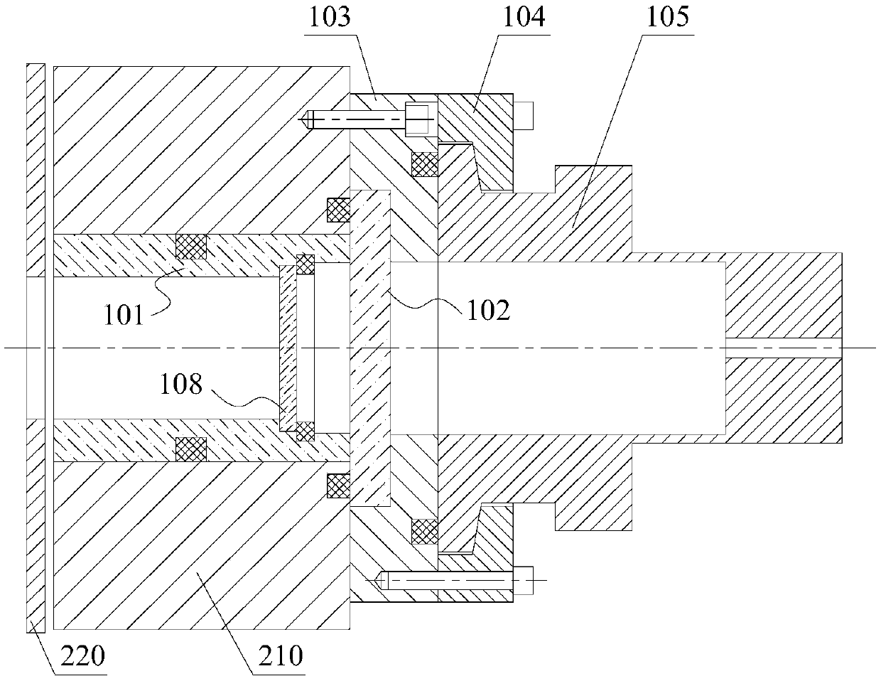
[0004] During installation, the above-mentioned parts need to be installed one by one on the wall 210 of the etching chamber. During disassembly, for the OES observation window sleeve 101 and the protective window 108 inside, the liner 220 needs to be disassembled and ejected from the opposite side. Excessive and time-consuming

Method used


Image

  • Optical signal collecting device and etching equipment
  • Optical signal collecting device and etching equipment
  • Optical signal collecting device and etching equipment

Examples


Embodiment approach

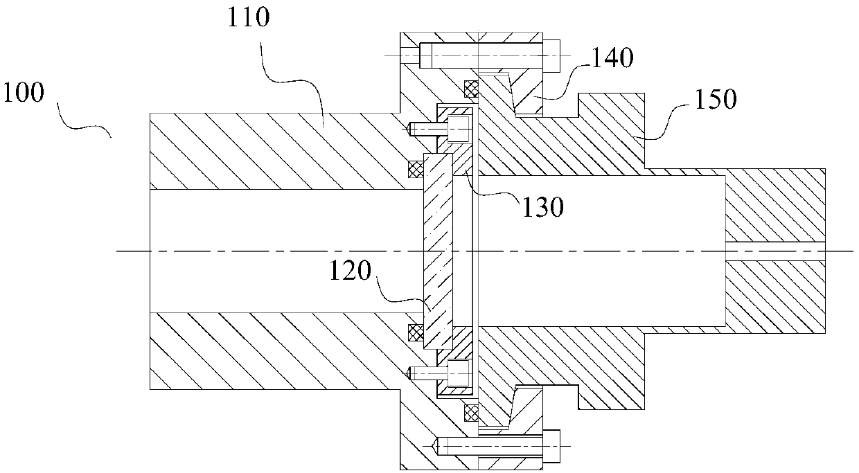
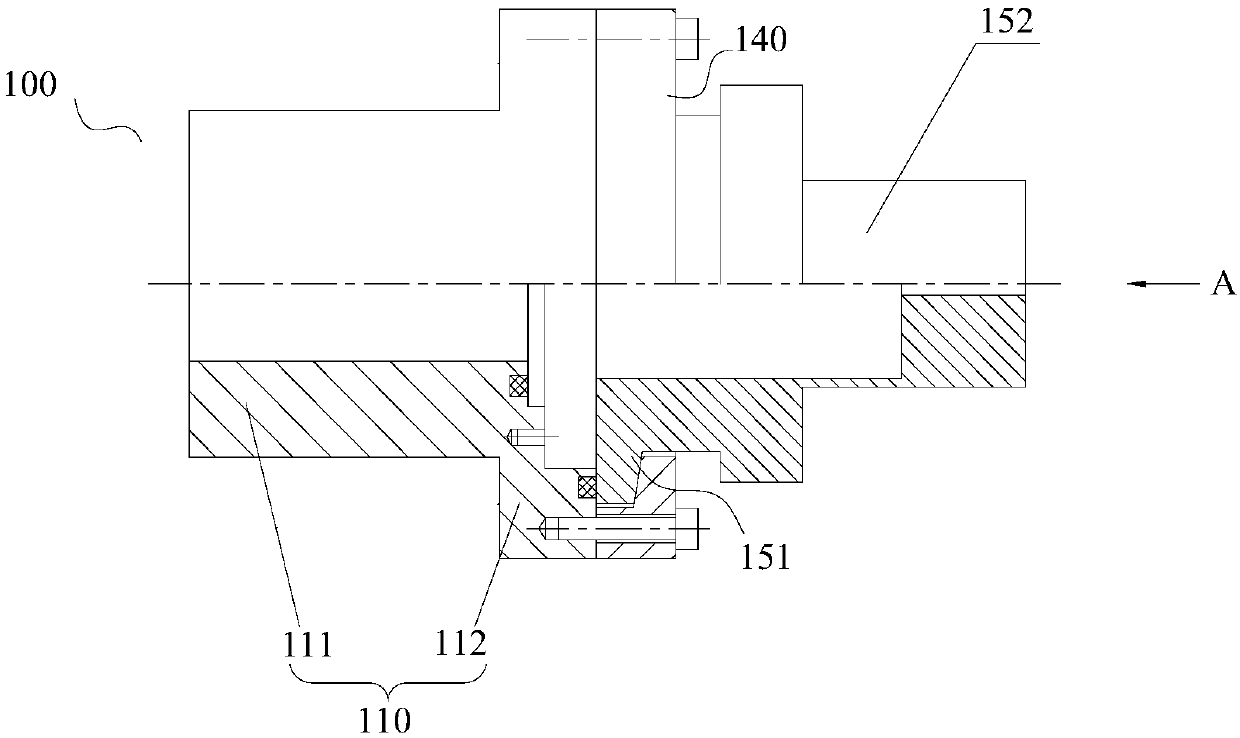
[0083] As a preferred embodiment of the present invention, when the installation sleeve 110 includes the installation cylinder portion 111 and the second fixing flange 112, the installation cylinder portion 111 of the installation sleeve 110 is arranged in the second installation hole 211, and the installation sleeve The second fixing flange 112 of 110 is detachably fixedly connected to the outside of the wall 210 of the etching chamber.

[0084] In order to prevent foreign matter from entering the etching chamber, further preferably, a seal is formed between the second fixing flange 112 and the outer surface of the wall 210 of the etching chamber. The forms of sealing include but are not limited to sealing rings, gaskets, and oil seals.

[0085]Compared with the scheme in the prior art where the cylindrical mounting sleeve is fully inserted into the second mounting hole 211 and a sealing ring is provided between the mounting sleeve and the second mounting hole 211, the mounti...


PUM


Abstract

The invention provides an optical signal collecting device. The optical signal collecting device comprises a mounting sleeve, an optical signal collecting piece and a light transmitting piece. The optical signal collecting piece comprises a light guide cavity, and an inlet of the light guide cavity of the optical signal collecting piece is formed in one end of the optical signal collecting piece.The mounting sleeve is fixedly connected with one end, where the inlet of the light guide cavity is formed, of the optical signal collecting piece. The light transmitting piece is arranged in the mounting sleeve or between the mounting sleeve and the optical signal collecting piece, and light emitted from the inner cavity of the mounting sleeve can penetrate through the light transmitting piece toenter the light guide cavity. The invention also provides etching equipment comprising the optical signal collecting device, and when the etching equipment is disassembled and assembled, the opticalsignal collecting device can be disassembled and assembled in an integral form, so that the time cost for disassembling and assembling the equipment can be saved, and the production efficiency can beimproved.

Description

technical field [0001] The present invention relates to the technical field of semiconductor manufacturing, in particular to an optical signal acquisition device and an etching device including the optical signal acquisition device. Background technique [0002] In the manufacturing process of integrated circuit (IC, Integrated Circuit), etching machine is an indispensable equipment. With the gradual reduction of etching process and the gradual complexity of wafer film structure, the control and monitoring of etching process become particularly important. The existing control method is mainly Optical Emission Spectroscopy (OES, Optical Emission Spectroscopy) method, which collects the spectrum of the plasma in the etching process, so as to realize the real-time monitoring of the plasma, and realizes the analysis and comparison of the spectrum. Process control. [0003] The structure of the existing optical signal acquisition device is as follows: figure 1 shown. Its key ...

Claims


Application Information

Patent Timeline
IPC IPC(8): H01J37/32
CPCH01J37/32972H01J37/32807H01J2237/3341
Inventor 侯文潭郭士选曹永友楼丰瑞石锗元
Owner BEIJING NAURA MICROELECTRONICS EQUIP CO LTD
Learn More