Controller system for and method of operating multiphase switched reluctance machine, and correction unit

A technology of multi-phase switching and reluctance motors, which is applied in the field of applying phase currents successively to supply power for each phase step.

Pending Publication Date: 2020-05-05
PUNCH POWERTRAIN NV
View PDF5 Cites 1 Cited by
  • Summary
  • Abstract
  • Description
  • Claims
  • Application Information

AI Technical Summary

Problems solved by technology

However, at higher speeds, it is no lo...

Method used


Image

  • Controller system for and method of operating multiphase switched reluctance machine, and correction unit
  • Controller system for and method of operating multiphase switched reluctance machine, and correction unit
  • Controller system for and method of operating multiphase switched reluctance machine, and correction unit

Examples


Embodiment Construction

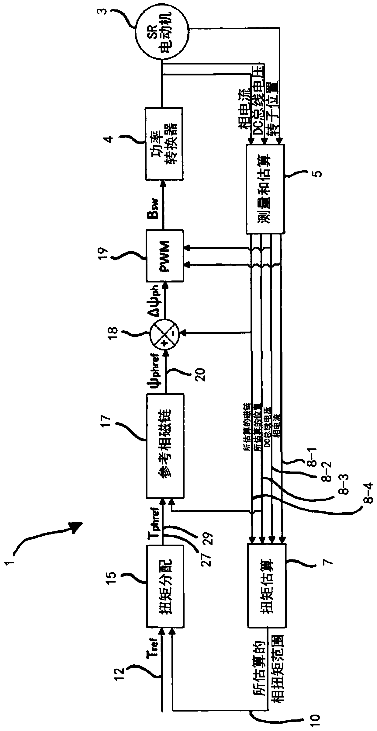
[0022] exist figure 1 A closed-loop controller system 1 for controlling a switched reluctance (SR) motor 3 is schematically illustrated in . The DC bus voltage and the phase current voltage of each of the respective phase steps of the switched reluctance (SR) motor 3 are measured and provided to the measurement and evaluation unit 5 . The measurement and evaluation unit 5 also receives a motor position signal, which can be obtained for example using a position encoder (not shown) in the SR motor 3 . From the obtained phase currents and rotor positions, the flux linkage of each phase step of the motor 3 is estimated.

[0023] The estimated flux linkage 8 - 4 , the position of the rotor 8 - 3 as well as the measured phase currents 8 - 1 and DC bus voltage 8 - 2 are passed to the torque estimation unit 7 . The torque estimation unit 7 is used to predict the range of deliverable phase torques for the corresponding phase steps. The torque estimation unit 7 may apply algorithms a...


PUM


Abstract

The present document relates to a controller system for operating a multiphase switched reluctance machine comprising a stator and a rotor, the rotor being rotatable relative to the stator. Each coilof the stator is associated with a phase stage, such that each phase stage is associated with a plurality of stator coils. The controller system is arranged for powering the phase stages by subsequently applying a phase current to each of the phase stages. For each phase stage the phase current is applied by switching on the phase current in a first position of a counter pole relative to a statorpole, and switching off the phase current in a second position of the counter pole. The controller comprises a torque distribution unit determining a desired torque output to be delivered by each phase stage for providing the desired torque output, and a correction unit for correcting the determined desired torque output, for enabling building up said phase current for enabling the phase stage toeffectively deliver the desired torque output as determined by the torque distribution unit. The document also describes a method.

Description

technical field [0001] The present invention relates to a controller system for operating a multiphase switched reluctance motor comprising a stator comprising a plurality of coils and stator poles, wherein each stator pole forms a magnetic core for the coils, and a rotor comprising A plurality of counter-poles for interacting with the poles of the stator to impart a reluctance torque to the rotor, the rotor is rotatable relative to the stator, the coils are associated with a plurality of phase steps of the multi-phase switched reluctance motor such that each coil of the stator is associated with Each phase step is thus associated with one or more of the plurality of coils of the stator; wherein the controller system is configured to sequentially apply phase current to supply each phase step to apply a reluctance torque to the rotor, where for each phase step the phase current is applied by switching on the phase in the first position of the counter pole relative to the stator...

Claims


Application Information

Patent Timeline
IPC IPC(8): H02P25/08H02P25/098
CPCH02P25/08H02P25/098
Inventor 陈琼忠S·贝尔沃茨G·巴比拉托
Owner PUNCH POWERTRAIN NV
Why Eureka
Try Eureka