Hybrid system control method

A technology of a hybrid system and control method, applied in the control device, engine control, transmission control and other directions, can solve the problem of no solution, unavoidable torque drop, etc., and achieve the effect of preventing torque drop

Active Publication Date: 2010-12-01
BOSCH CORP
View PDF6 Cites 21 Cited by
  • Summary
  • Abstract
  • Description
  • Claims
  • Application Information

AI Technical Summary

Problems solved by technology

In an automatic transmission (AT), in order to reduce the shift shock and time lag when shifting gears, for example, an attempt is made to adjust the shift shock and time lag so that the driver hardly notices them using overall coordination with the engine and half-clutch control levels that have occurred, but this does not form an adequate solution
In addition, in automated manual transmissions (AMT), torque drops due to long lags when shifting upshifts are largely unavoidable

Method used


Image

  • Hybrid system control method
  • Hybrid system control method
  • Hybrid system control method

Examples


Embodiment Construction

[0055] Embodiments of the present invention will be described below with reference to the accompanying drawings.

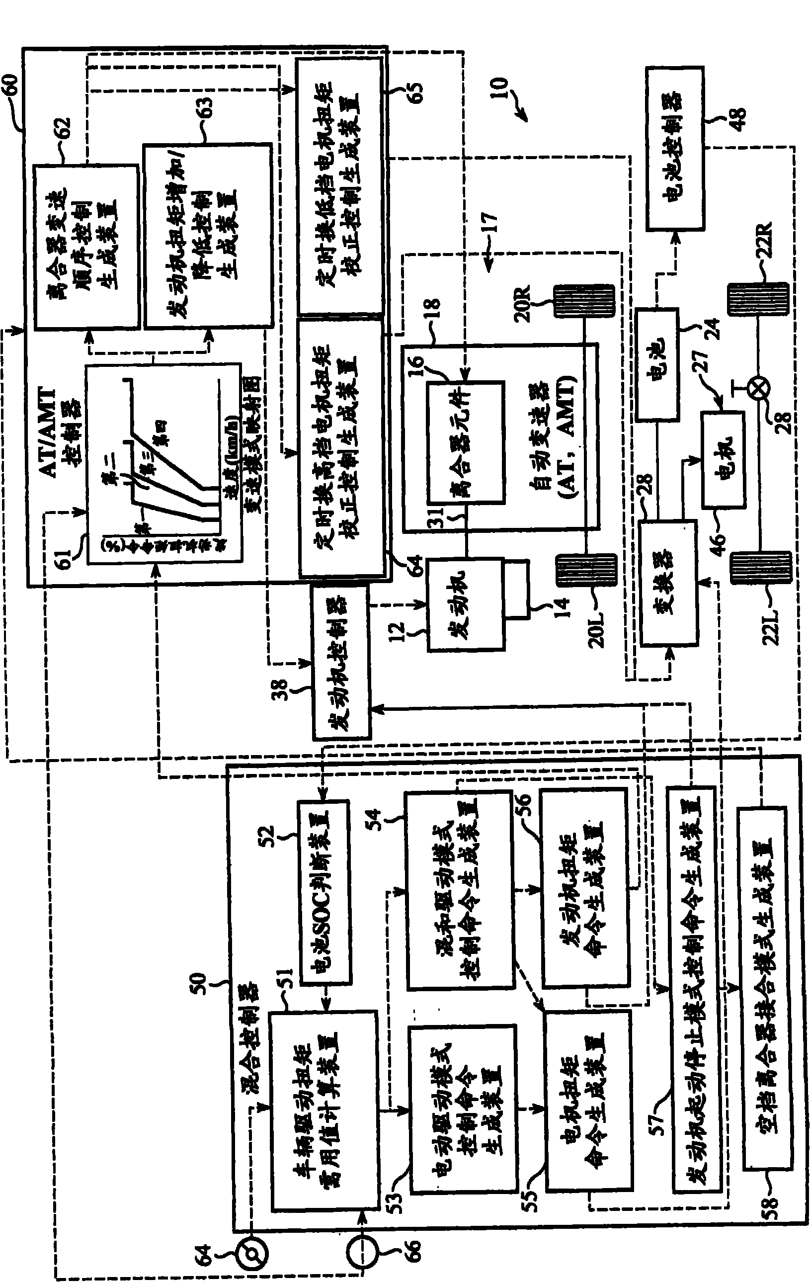
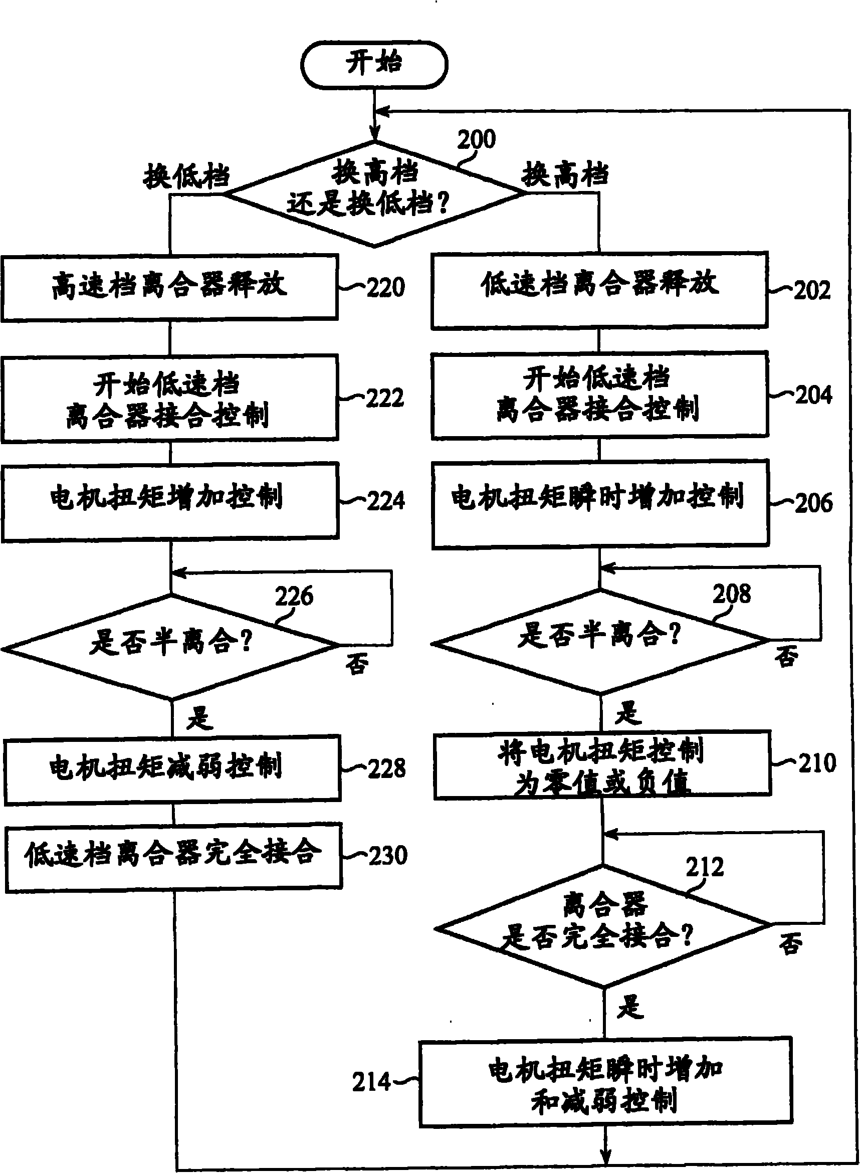
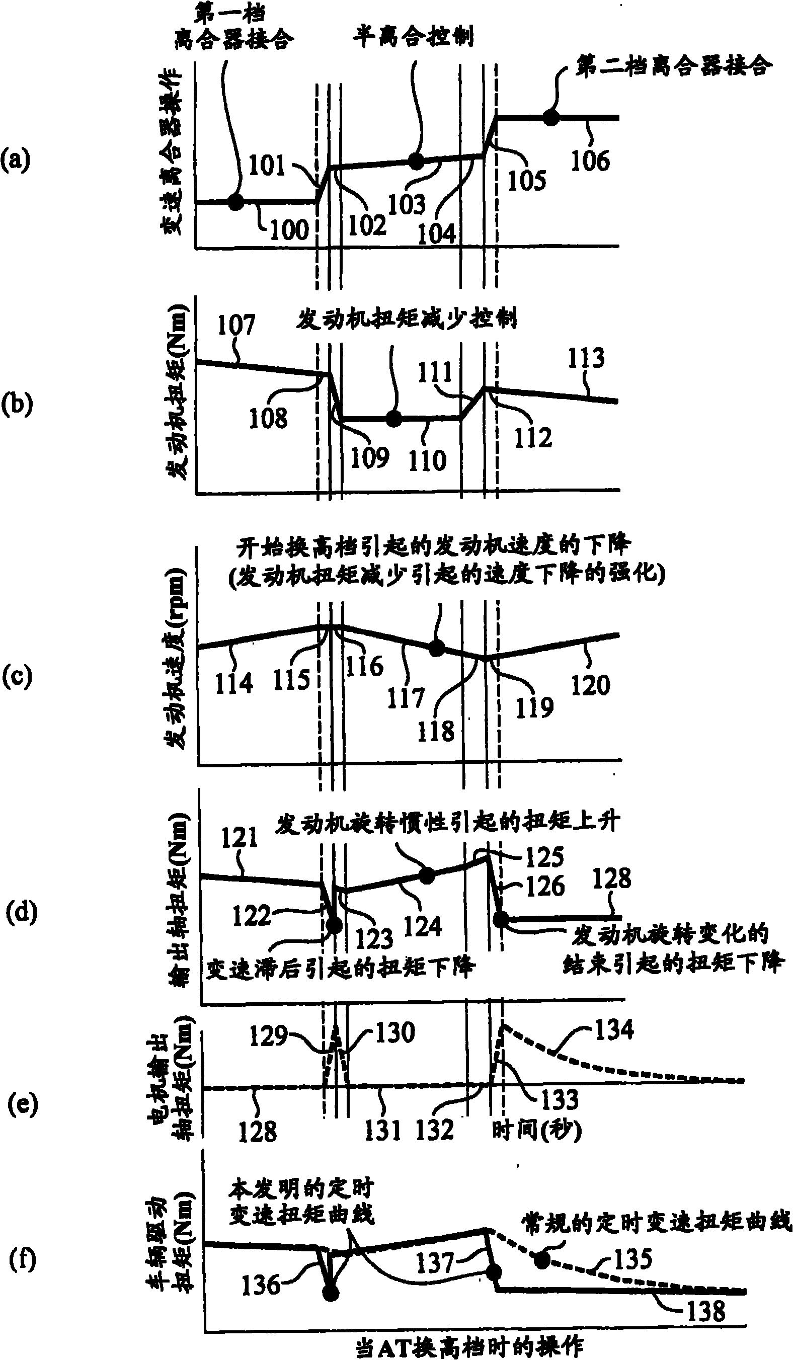
[0056] exist figure 1 In , a vehicle 10 to which the hybrid system control method belonging to the first embodiment of the present invention is applied and a control system of the vehicle 10 capable of realizing the control of the hybrid system are shown. The vehicle 10 is a four-wheel drive hybrid vehicle in which the electric drive axle unit is arranged on the driven axle of an existing two-wheel drive vehicle so as to be constructed with minimal vehicle modification, and the vehicle 10 is equipped with an internal combustion engine 12 for starting The starter motor 14 of the engine 12, the first drive system 17 for transmitting the drive force of the internal combustion engine to the shafts of the front wheels 20L and 20R, the battery 24, and the first drive system for supplying electric drive power to the shafts of the rear wheels 22L and 22R Two drive systems ...


PUM


Abstract

It is possible to reduce the torque drop caused by a transmission shock and a time lag in a hybrid system. When the transmission speed ratio is up-shifted in a hybrid system control method, a motor torque is instantaneously increased upon start of a half clutch control of a clutch and the motor torque is controlled to be zero or minus to compensate a vehicle drive torque increase by the engine rotation inertia during the half clutch control. When the clutch is completely connected, the motor torque is increased.After the increase of the torque, the motor torque is decreased with a predetermined time constant. When down-shift is performed, the motor torque is increased upon start of the half clutch control and the motor torque is decreased with a predetermined time constant from the increased torque so as to compensate the lowering of the vehicle drive torque by the engine rotation inertia, thereby smoothly making a connection to a torque-up amount upon a complete clutch connection.

Description

technical field [0001] The present invention relates to a hybrid system control method for reducing torque drop due to shift shock and time lag occurring during transmission shifting, for example in a shaft-split hybrid system. Background technique [0002] In JP-A-2004-034816, a method is disclosed in which a transmission is arranged between the engine and the drive wheels, an electric motor is arranged on one shaft of this transmission, and torque correction caused by the electric motor prevents shifting in the transmission The reduction in the driving force of the vehicle caused by the fluctuation of engine torque, etc. Specifically, the engine output shaft torque is detected, the driving force fluctuation portion of the vehicle is calculated, and this driving force fluctuation portion of the vehicle is corrected by torque correction measures caused by the motor. That is, in order to avoid a state in which the engine output torque is not transmitted, which occurs instant...

Claims


Application Information

Patent Timeline
Patent Type & Authority Applications(China)
IPC IPC(8): B60W10/08B60K6/442B60K6/52B60K6/547B60W10/02B60W10/06B60W10/10B60W20/00F02D29/00F02D29/02F16H61/04F16H63/40F16H61/684B60L50/16B60W30/18
CPCY02T10/6286B60W2520/10B60W2710/081B60W10/115B60W10/10B60W10/06B60W10/02B60K6/547B60L2240/421B60W2710/0666Y02T10/6265B60W10/11B60W10/08Y02T10/6221F16H63/502B60L2240/423F16H61/0437F16H2061/0433B60K6/48B60W2710/083B60K6/365B60W20/00F02D29/02B60K6/52Y02T10/642B60W30/19B60W20/108B60W20/15Y02T10/62Y02T10/64B60W20/40
Inventor 今关隆志
Owner BOSCH CORP
Why Eureka
Try Eureka