Drilling machine

A technology of drilling machine and drill bit, which is applied in the direction of boring/drilling, drilling/drilling equipment, metal processing machinery parts, etc. Effect

Active Publication Date: 2020-05-08
东莞市华盛精密模具配件有限公司
View PDF6 Cites 2 Cited by
  • Summary
  • Abstract
  • Description
  • Claims
  • Application Information

AI Technical Summary

Problems solved by technology

[0003] In the process of drilling the pipeline, in order to ensure that the two end holes of the pipeline are on the diameter of the existing drilling machine, the pipeline is fixed and drilled from the vertical downward, and the debris generated after the top hole is drilled Under the action of gravity, it falls to the lowest point of the pipeline, blocking another drilling point, and due to the presence of debris, the friction between the drill bit and the drilling point is increased

Method used


Image

  • Drilling machine
  • Drilling machine
  • Drilling machine

Examples


Embodiment 1

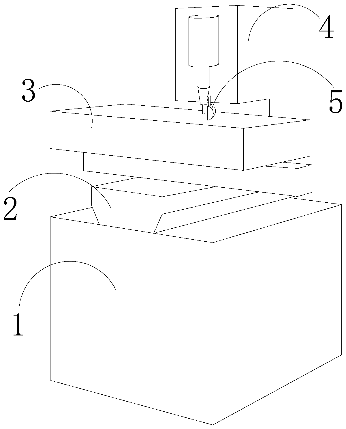
[0025] see Figure 1-Figure 4 , the present invention provides a drilling machine, the structure of which includes a fixed seat 1, a connecting seat 2, a processing table 3, a drill bit connecting seat 4, and a slag collecting device 5. The fixed seat 1 is provided with a connecting seat 2, and the connecting seat 2 The seat 2 is fixedly connected with the processing table 3, the processing table 3 is mechanically connected with the drill bit connecting seat 4, and the drill bit connecting seat 4 is connected with the slag collecting device 5;

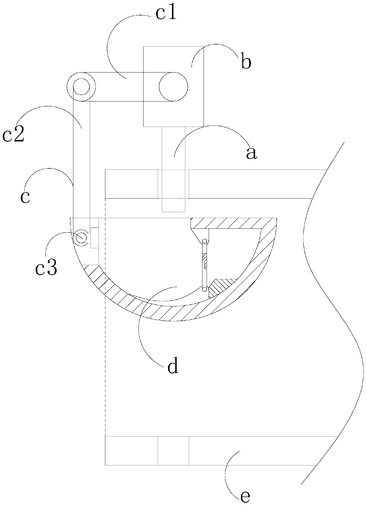
[0026] The slag collection device 5 is composed of a drill bit a, a drill bit connecting block b, a rotating mechanism c, a slag collecting tank d, and a steel pipe e. The drill bit a is connected to the drill bit connecting block b, and the drill bit connecting block b is connected to the drill bit connecting seat 4 Mechanical connection, the drill bit a is mechanically matched with the steel pipe e, the steel pipe e is matched with t...

Embodiment 2

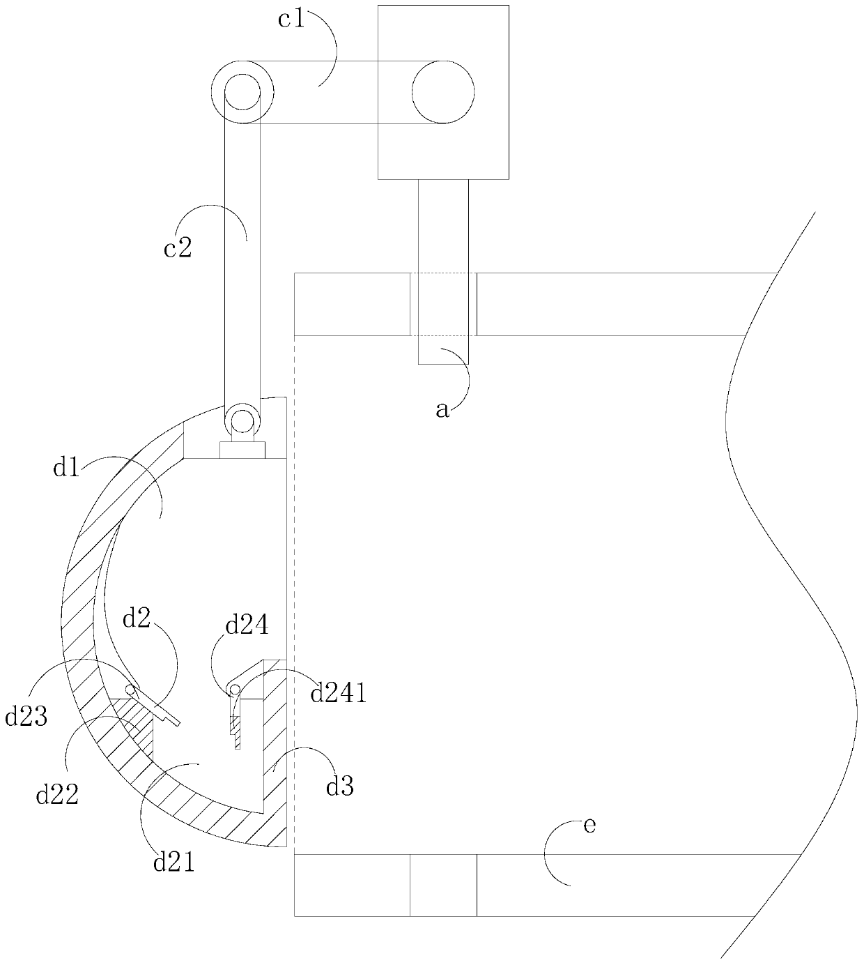
[0036] see Figure 1-Figure 3 , the present invention provides a drilling machine, the structure of which includes a fixed seat 1, a connecting seat 2, a processing table 3, a drill bit connecting seat 4, and a slag collecting device 5. The fixed seat 1 is provided with a connecting seat 2, and the connecting seat 2 The seat 2 is fixedly connected with the processing table 3, the processing table 3 is mechanically connected with the drill bit connection seat 4, and the drill bit connection seat 4 is connected with the slag collecting device 5; the slag collecting device 5 is composed of a drill bit a and a drill bit connecting block b , a rotating mechanism c, a slag collecting tank d, and a steel pipe e; the slag collecting tank d is composed of a No. 1 chamber d1, a slag inlet d2, and a solid block d3. The solid block d3 is connected with the first cavity d1, and the slag inlet d2 is mechanically connected with the solid block d3; the slag inlet d2 is composed of the second ...


PUM


Abstract

The invention discloses a drilling machine. The drilling machine structurally comprises a fixing seat, a connecting seat, a machining table, a drill bit connecting seat and a chipping collecting device, wherein the fixing seat is provided with the connecting seat, the connecting seat is fixedly connected with the machining table, the machining table is mechanically connected with the drill bit connecting seat, and the drill bit connecting seat is connected with the chipping collecting device. The drilling machine has the beneficial effects that chippings generated in the steel pipe drilling process are collected through arranging a chipping collecting groove, so that the chippings generated in the drilling process are prevented from falling off and blocking another drilling point; meanwhile, a solid balance weight layer is arranged at the end, close to a first plate, of a second plate so that the force application direction of the second plate can be always vertically downward, and when the chipping collecting groove rotates anticlockwise by 90 degrees, a second cavity is in a closed state; and when the chipping collecting groove is reset, the second cavity is opened, so that the chippings in a first cavity enters the second cavity and are prevented from flying out of the chipping collecting groove under the action of centrifugal force in the rotating process, and meanwhile theproblem that drill bit abrasion is aggravated due to the existence of the chipping can be effectively solved.

Description

technical field [0001] The invention relates to the field of drilling machines, in particular to a drilling machine. Background technique [0002] With the development of science and technology, a variety of mechanical equipment has been developed and gradually improved. During the assembly of mechanical parts, some parts need to be drilled to facilitate the assembly between parts. The current drilling machine has the following defects: [0003] In the process of drilling the pipeline, in order to ensure that the two end holes of the pipeline are on the diameter of the existing drilling machine, the pipeline is fixed and drilled from the vertical downward, and the debris generated after the top hole is drilled Under the action of gravity, it falls to the lowest point of the pipeline, blocking another drilling point, and due to the presence of debris, the friction between the drill bit and the drilling point is increased. Contents of the invention [0004] Aiming at the de...

Claims


Application Information

Patent Timeline
Patent Type & Authority Applications(China)
IPC IPC(8): B23B41/00B23Q11/00
CPCB23B41/00B23Q11/0042
Inventor 苏燕芳
Owner 东莞市华盛精密模具配件有限公司
Why Eureka
Try Eureka