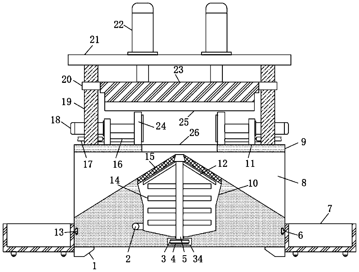
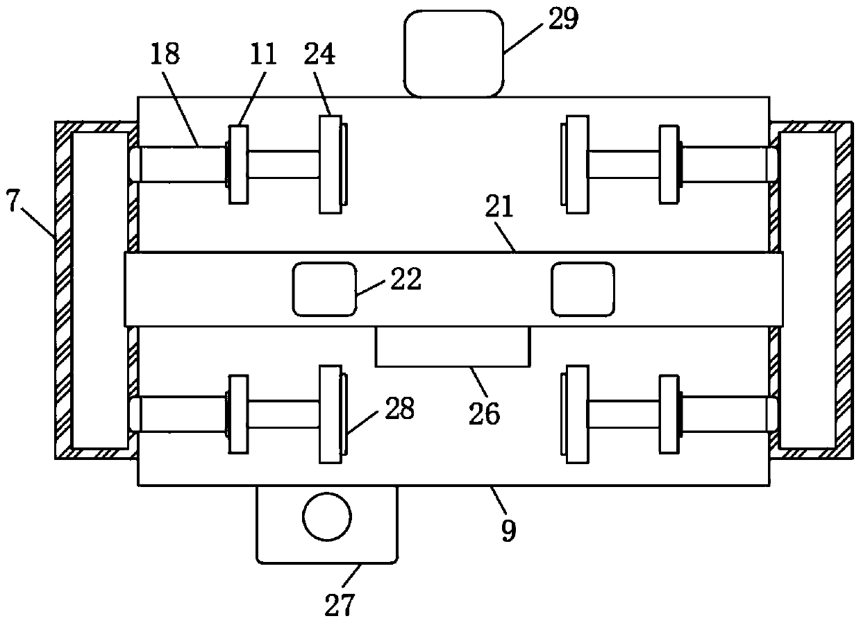
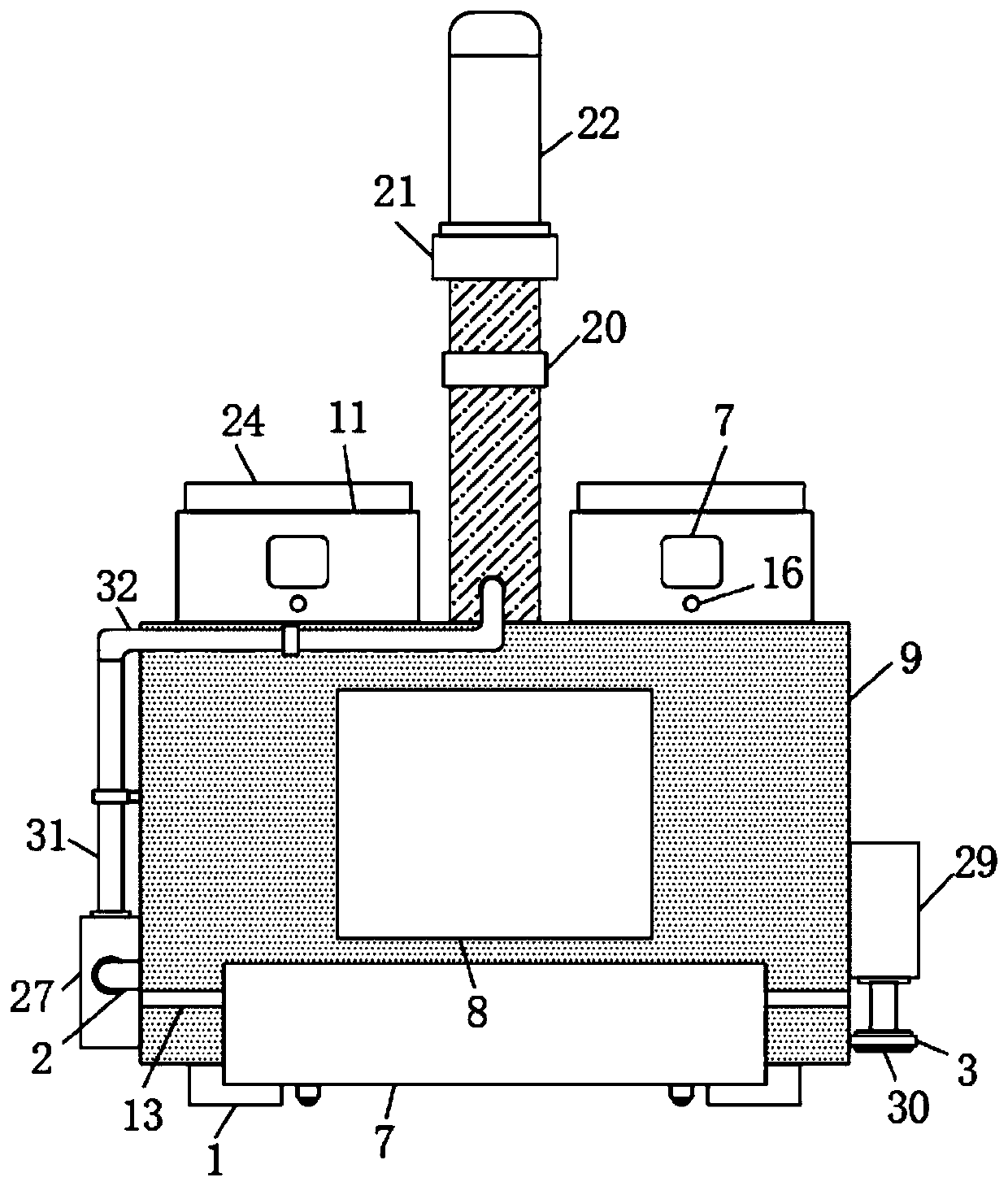
Novel rod hydraulic head cutting and tail cutting scissors

A kind of tail shearing and hydraulic technology, which is applied in the direction of shearing device, shearing machine equipment, accessories of shearing machine, etc., to achieve the effect of ensuring accuracy, reducing waste and improving stability

Inactive Publication Date: 2020-05-08
福州英迪特智能科技有限公司
View PDF8 Cites 7 Cited by
  • Summary
  • Abstract
  • Description
  • Claims
  • Application Information

AI Technical Summary

Problems solved by technology

[0004] The purpose of the present invention is to solve the shortcomings in the prior art, and propose a new type of rod hydraulic head and tail cutting shears, which can directly drop the leftovers from the head and tail into the collection box for collection , no need to manually pick up and collect, which can reduce the workload of the staff, and the cutting fluid can be filtered and reused, which improves the use effect of the cutting fluid and avoids the clogging of the liquid storage chamber

Method used


Image

  • Novel rod hydraulic head cutting and tail cutting scissors
  • Novel rod hydraulic head cutting and tail cutting scissors
  • Novel rod hydraulic head cutting and tail cutting scissors

Examples


Embodiment Construction

[0025] The following will clearly and completely describe the technical solutions in the embodiments of the present invention with reference to the accompanying drawings in the embodiments of the present invention. Obviously, the described embodiments are only some, not all, embodiments of the present invention.

[0026] In describing the present invention, it should be understood that the terms "upper", "lower", "front", "rear", "left", "right", "top", "bottom", "inner", " The orientation or positional relationship indicated by "outside", etc. is based on the orientation or positional relationship shown in the drawings, and is only for the convenience of describing the present invention and simplifying the description, rather than indicating or implying that the referred device or element must have a specific orientation, so as to Specific orientation configurations and operations, therefore, are not to be construed as limitations on the invention.

[0027] refer to Figure ...


PUM


Abstract

The invention discloses novel rod hydraulic head cutting and tail cutting scissors comprising a machine body. A plurality of support seats are fixedly connected to the lower end of the machine body. Two vertical rods are symmetrically arranged on the upper side of the machine body and are fixedly connected. The upper ends of the two vertical rods are jointly fixedly connected with an installationplate. Two second hydraulic oil cylinders are fixedly connected to the upper side of the installation plate. A lifting plate is arranged between the two vertical rods. The two vertical rods are each sleeved with a sliding barrel capable of moving up and down. Both the two sliding barrels are fixedly connected with the lifting plate. A cutter is fixedly connected to the lower side of the lifting plate. The novel rod hydraulic head cutting and tail cutting scissors are reasonable in structural design, excess materials cut off from the head and the tail can directly fall into a collection box tobe collected, manual picking and collection are not needed, the workload of a worker can be reduced, in addition, cutting fluid can be filtered and reused, the use effect of the cutting fluid is improved, and meanwhile, a blocking condition in a fluid storage cavity is avoided.

Description

technical field [0001] The invention relates to the technical field of hydraulic cutting devices, in particular to a novel rod hydraulic head and tail cutter. Background technique [0002] The shearing machine is suitable for metal recycling processing plants, scrapped car dismantling sites, smelting and casting industries, for cold shearing, pressing and flanging of various shapes of steel and various metal materials, as well as powder products, plastics, glass steel, insulation, etc. Press molding of materials and rubber. The shearing machine is divided into different types: metal shearing machine, combined punching and shearing machine, hydraulic shearing machine, bar shearing machine. The most commonly used metal shears are crocodile shears and gantry shears. [0003] In the prior art, since the head and tail of the bar often need to be sheared, in the process of cutting the head and tail of the bar shear, the remaining material at the head and tail will directly fall ...

Claims


Application Information

Patent Timeline
Patent Type & Authority Applications(China)
IPC IPC(8): B23D31/00B23D33/02B23Q11/00B23Q11/10B21D43/00B21D43/20
CPCB21D43/003B21D43/20B23D31/00B23D33/02B23Q11/00B23Q11/0042B23Q11/10B23Q11/1069Y02P70/10
Inventor 黄锦红王兵
Owner 福州英迪特智能科技有限公司
Why Eureka
Try Eureka