
3D printing back drawing motion track planning method

A motion trajectory, 3D printing technology, applied in the field of 3D printing, can solve the problems of material accumulation, lack of material, wire drawing, etc., to achieve the effect of improving printing quality, avoiding wire drawing, and improving speed

Pending Publication Date: 2020-05-08
上海酷鹰机器人科技有限公司
View PDF0 Cites 5 Cited by
  • Summary
  • Abstract
  • Description
  • Claims
  • Application Information

AI Technical Summary

Problems solved by technology

[0010] The embodiment of the present application provides a 3D printing retraction motion trajectory planning method, which solves the technical problems such as wire drawing, material accumulation, and lack of material that are easily generated by the retraction motion in the prior art, so that large-scale products with a retraction path can also be Realized by 3D printing, and effectively improved the printing quality of 3D printed components

Method used


Image

  • 3D printing back drawing motion track planning method
  • 3D printing back drawing motion track planning method
  • 3D printing back drawing motion track planning method

Examples


Embodiment Construction

[0039] The embodiments of the present application provide a 3D printing retraction motion trajectory planning method, which solves the technical problems such as wire drawing, material accumulation, and material shortage that are easily generated by retraction motion in the prior art, ensures the integrity of trajectory printing, and has Large-scale products with a retraction path can also be realized by 3D printing, which effectively improves the printing quality of 3D printed components.

[0040] The technical solutions in the embodiments of the present application are to solve the above-mentioned problem of crosstalk, and the general idea is as follows:

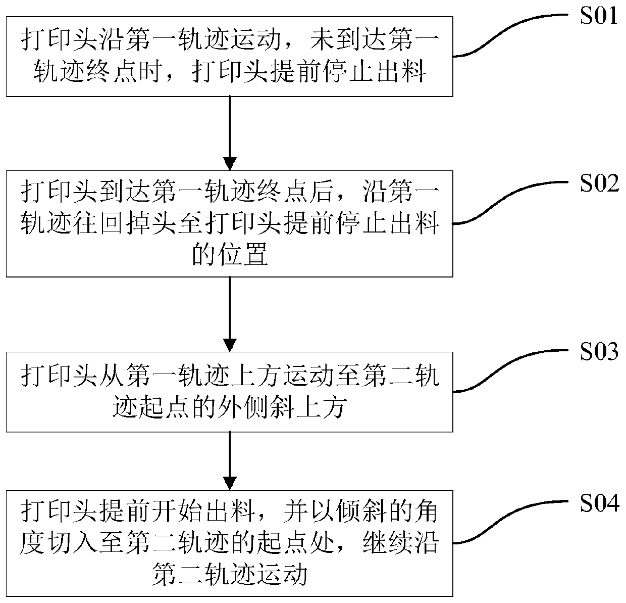
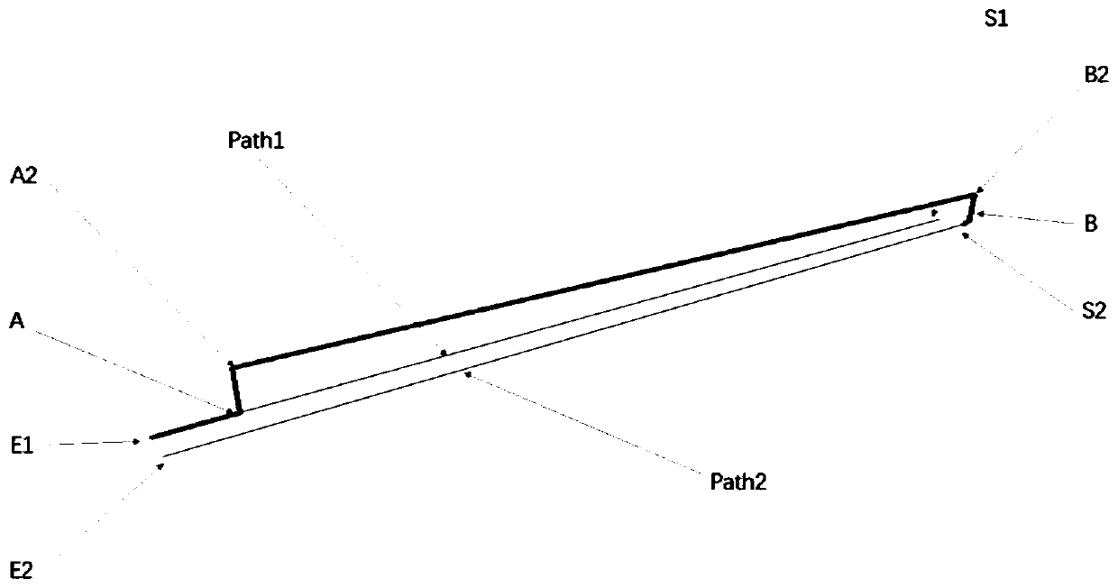
[0041] Between the first trajectory and the second trajectory of 3D printing, the retraction motion trajectory needs to be planned, and a new 3D printing retraction motion trajectory planning method is designed, such as figure 1 shown, including the following steps:

[0042] S01: The print head moves along the first track...


PUM


Abstract

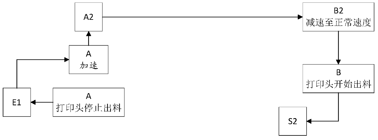
The invention discloses a 3D printing back drawing motion track planning method. A back drawing motion track is planned between a first track and a second track of 3D printing. The method includes theprocesses that a printing head moves along the first track, and when the printing head does not reach the end point of the first track, the printing head stops conducting discharging in advance; after the printing head moves to the end point of the first track, the printing head turns around back along the first track to reach the position where discharging is stopped in advance; the printing head moves to the position above the outer side of the starting point of the second track from the position above the first track; and discharging begins when the printing head does not reach the starting point of the second track, the printing head is switched to the starting point of the second track with a downward switching inclined angle and moves continuously along the second track. By means ofthe 3D printing back drawing motion track planning method, the printing head stops discharging in advance and turns round back when back drawing begins, and the phenomena of wire drawing and materialaccumulating of back drawing are avoided; and when back drawing is over, the printing head conducts discharging in advance and is switched to the track of the next segment with the inclined angle, the phenomenon of shortage of the printing track due to delayed discharging of the spray head is avoided, large components can be printed, and the component printing quality is greatly improved.

Description

technical field [0001] The invention relates to the technical field of 3D printing, in particular to a method for planning a 3D printing retraction motion trajectory. Background technique [0002] 3D printing is a kind of rapid prototyping technology, which is a technology that builds objects by layer-by-layer printing based on digital model files, using adhesive materials such as powdered metal or plastic. [0003] The design process of 3D printing is as follows: for the components to be printed, first use computer modeling software to model, and then "partition" the built 3D model into layer-by-layer sections, that is, slice, to obtain a printing program, which instructs the printer to print layer by layer. . [0004] During the slicing process, the obtained print program is essentially a movement track line formed by connecting a large number of points. The motion trajectory of each layer is an array of polylines. That is to say, the printing program obtained by slicin...

Claims


Application Information

Patent Timeline
Patent Type & Authority Applications(China)
IPC IPC(8): B29C64/112B29C64/118B29C64/386B33Y10/00B33Y50/00
CPCB29C64/112B29C64/118B29C64/386B33Y10/00B33Y50/00
Inventor 张昱周明
Owner 上海酷鹰机器人科技有限公司
Learn More