
Driving control method, system and device of electric vehicle

A driving control, electric vehicle technology, applied in electric vehicles, control drive, transportation and packaging, etc., can solve problems such as performance and driving experience need to be further improved, immature technology, etc., to improve operating experience, facilitate model matching, improve performance effect

Active Publication Date: 2020-05-08
BEIDOU AEROSPACE AUTOMOBILE BEIJING CO LTD
View PDF12 Cites 1 Cited by
  • Summary
  • Abstract
  • Description
  • Claims
  • Application Information

AI Technical Summary

Problems solved by technology

Due to its smaller impact on the environment than traditional cars, its prospects are widely optimistic, but the current technology is still immature, especially the performance and driving experience of cars need to be further improved

Method used


Image

  • Driving control method, system and device of electric vehicle
  • Driving control method, system and device of electric vehicle
  • Driving control method, system and device of electric vehicle

Examples


Embodiment 1

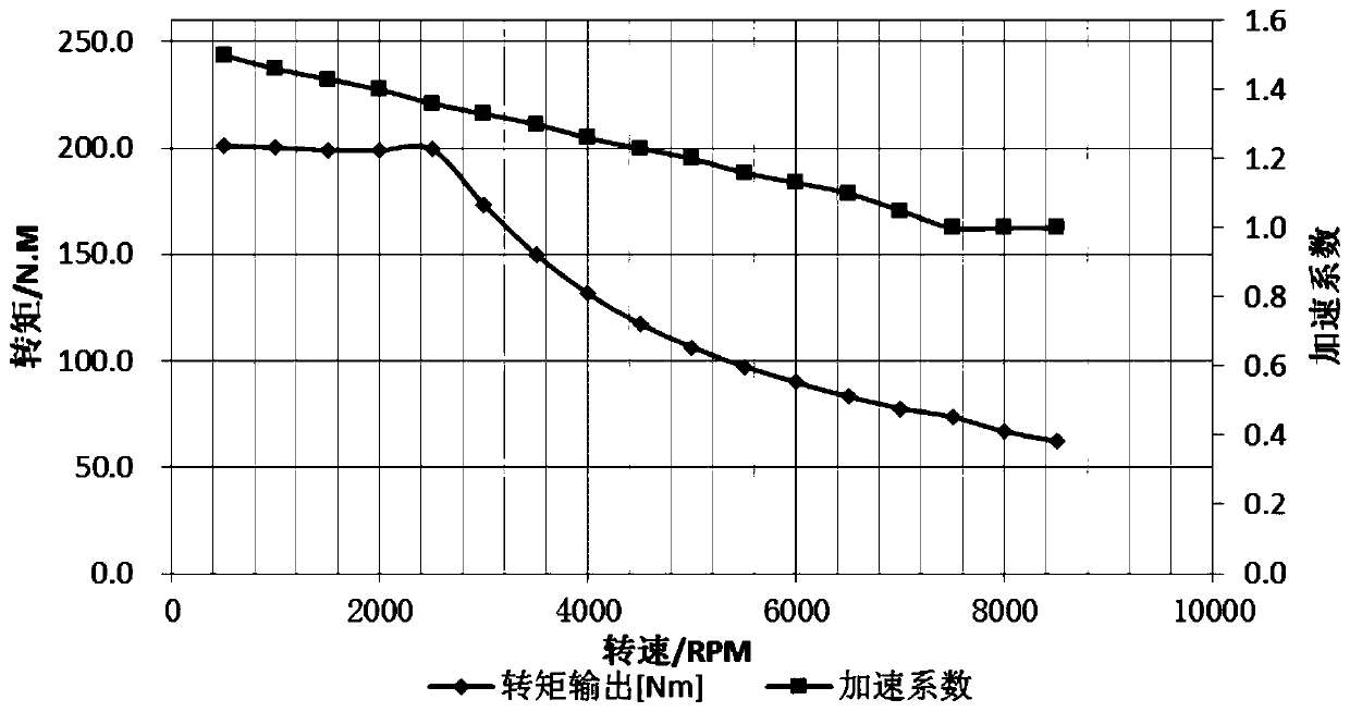
[0078] The driving control method of the electric vehicle has such as figure 1 The multiple rotational speeds shown, the maximum torque value corresponding to each rotational speed, the multiple rotational speeds and the acceleration coefficient corresponding to each rotational speed, wherein the interval between the rotational speeds is 500rpm;

[0079] Obtain the current motor speed, and calculate the maximum torque value corresponding to the current motor speed through the difference calculation formula a;

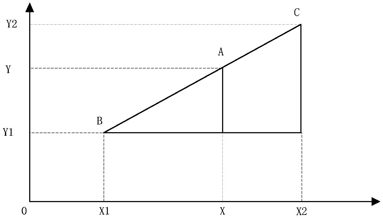
[0080] Formula a:

[0081] Y represents the maximum torque value corresponding to the current motor speed, X represents the current motor speed, X1 and X2 are the previous and next speeds that are closest to the current motor speed in the storage database, and Y1 and Y2 are the corresponding previous speeds and the maximum torque value of the latter speed, see the schematic diagram figure 2 ;

[0082] Calculate the acceleration coefficient corresponding to the cur...

Embodiment 2

[0090] The driving control system of electric vehicles, including: monitoring module, storage module, data processing module, control module and detection module;

[0091] The monitoring module is used to obtain the current motor speed;

[0092] The storage module is used to store multiple rotation speeds and the maximum torque value corresponding to each rotation speed and the acceleration coefficient corresponding to each rotation speed. For the corresponding values, see figure 1 ;

[0093] The data processing module is used to locate the current motor speed in the first storage module and the second storage module, and obtain the closest previous speed and next speed of the current motor speed and the corresponding maximum torque value and acceleration coefficient, and Calculate the maximum torque value and acceleration coefficient corresponding to the current motor speed through formula a and formula b, and put the obtained maximum torque value and acceleration coefficien...


PUM


Abstract

The invention relates to the technical field of electric vehicle control, in particular to a driving control method, system and device for an electric vehicle. The control method comprises the following steps: obtaining the current motor rotating speed, and obtaining the maximum torque value corresponding to the current motor rotating speed through difference calculation; obtaining an acceleration coefficient corresponding to the current motor rotating speed through the difference calculation; collecting the opening percentage of the current accelerator pedal; obtaining a final torque valueis obtained through calculation according to a formula c, and adjusting the rotating speed of the motor according to the final torque value so as to control running of the electric vehicle, wherein the formula c is that the final torque value is equal to the current accelerator pedal opening percentage * Y * Z. Therefore, the rotating speed of the motor is controlled by continuously outputting thefinal torque value, the driving speed of the electric vehicle is better controlled, the operation experience of a driver is greatly improved, and the method is suitable for all electric vehicles, high in adaptability and wide in application range.

Description

technical field [0001] The invention relates to the technical field of control of electric vehicles, in particular to a driving control method of electric vehicles, a system and a device thereof. Background technique [0002] Electric vehicles are powered by vehicle-mounted power supplies, driven by motors to drive wheels, and meet the requirements of road traffic and safety regulations. Due to its smaller impact on the environment than traditional cars, its prospects are widely optimistic, but the current technology is still immature, especially the performance and driving experience of cars need to be further improved. Contents of the invention [0003] In order to better improve the performance and driving experience of the car, the vehicle has different driving force output at each stage of driving. With the same accelerator pedal stroke, the vehicle needs to have greater acceleration performance in the initial stage, and the vehicle needs to be more stable when drivin...

Claims


Application Information

Patent Timeline
Patent Type & Authority Applications(China)
IPC IPC(8): B60W10/08B60W40/00B60L15/20
CPCB60L15/20B60W10/08B60W40/00Y02T10/72
Inventor 刘贵生张鹏苍海涛李志强
Owner BEIDOU AEROSPACE AUTOMOBILE BEIJING CO LTD
Learn More