
Floating crane swing reducing device

A swing reducing device and floating crane technology, applied in transportation and packaging, load hanging components, cranes, etc., can solve problems such as reducing the efficiency of hanging objects in place, increasing the construction cost of ship nesting, and difficulty in positioning hanging objects. , to achieve the effect of reducing construction costs and waste of resources, good project utilization value, and reducing the difficulty of hanging objects in place

Pending Publication Date: 2020-05-08
CCCC SECOND HARBOR ENG
View PDF0 Cites 4 Cited by
  • Summary
  • Abstract
  • Description
  • Claims
  • Application Information

AI Technical Summary

Problems solved by technology

[0003] 1) Under the excitation of the hull motion, the hook and rigging system will undergo forced vibration. When the natural vibration frequency of the hook system is relatively close to the response frequency of the hull motion, harmful large swings will occur, which will give the positioning belt of the hanging object It is very difficult, which reduces the efficiency of hanging objects in place
[0004] 2) The shimmy vibration of the ship's hoisting system during the hoisting process poses a threat to the personal safety of deck operators, and the waiting period of the window increases the construction cost and causes serious waste of resources

Method used


Image

  • Floating crane swing reducing device
  • Floating crane swing reducing device
  • Floating crane swing reducing device

Examples


Embodiment Construction

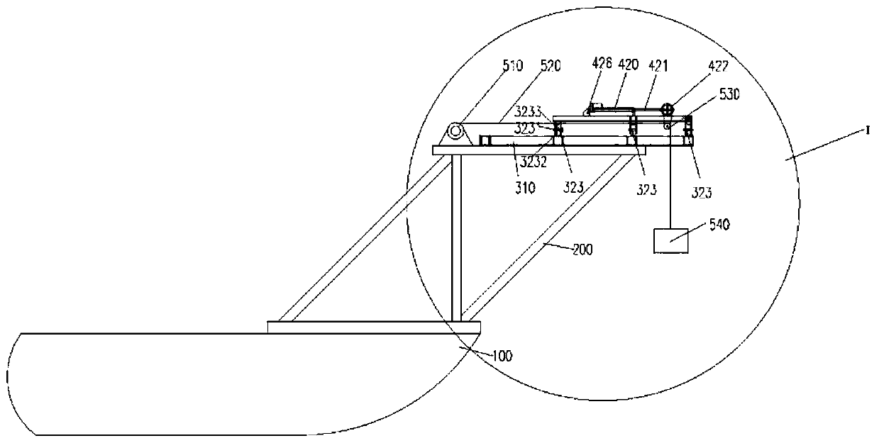
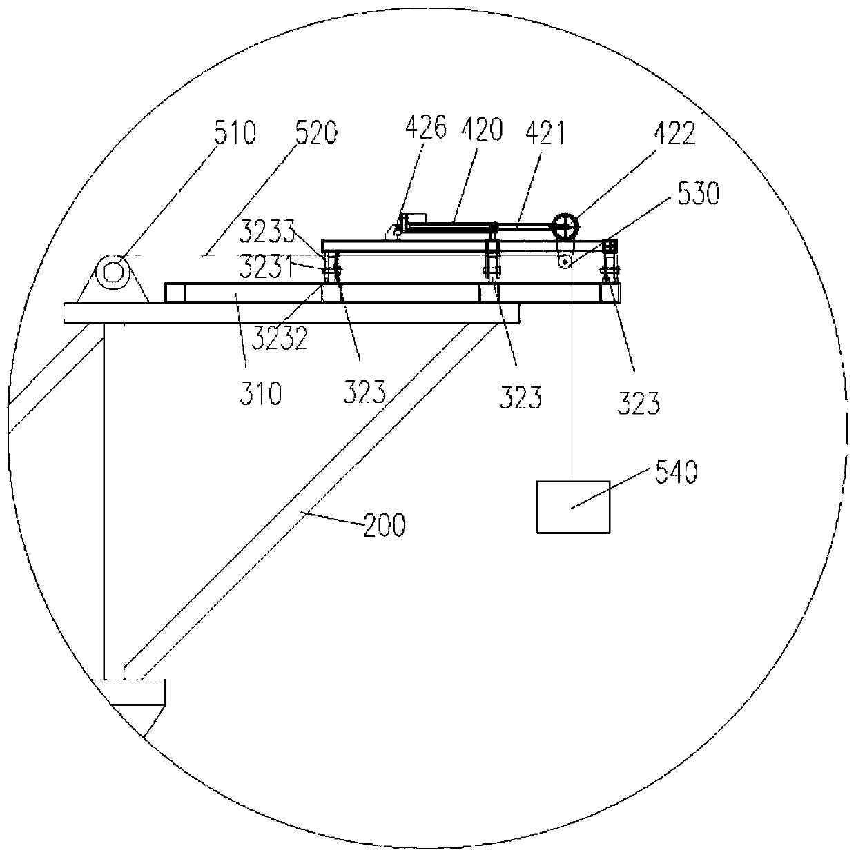
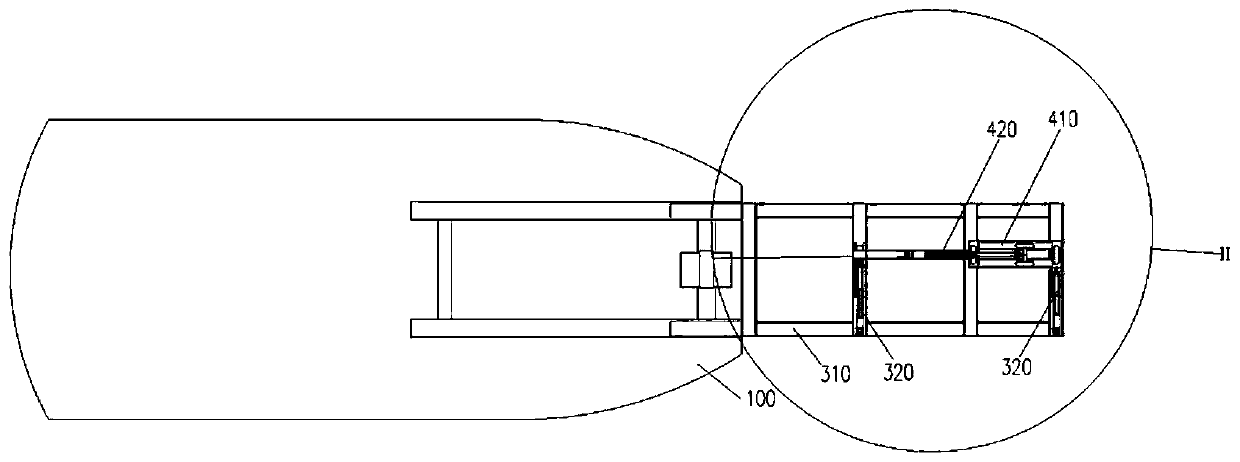
[0028] The present invention will be further described in detail below in conjunction with the accompanying drawings, so that those skilled in the art can implement it with reference to the description.

[0029] It should be understood that terms such as "having", "comprising" and "including" used herein do not exclude the presence or addition of one or more other elements or combinations thereof.

[0030] Such as Figure 1-4 As shown, in order to achieve these objects and other advantages according to the present invention, a floating crane sway reduction device is provided, which is applied to a water ship 100 for hoisting operations. The ship 100 is provided with an outwardly extending floating crane bracket 200, and the floating crane A winch 510 is provided on the bracket 200, which includes a longitudinal damping mechanism and a transverse damping mechanism. The longitudinal damping mechanism includes a first bracket 310 and at least two first electric cylinders 320. The...


PUM


Abstract

The invention discloses a floating crane swing reducing device. The floating crane swing reducing device comprises a longitudinal damping mechanism and a transverse damping mechanism. The longitudinaldamping mechanism comprises a first bracket and at least two first electric cylinders. The two first electric cylinders are longitudinally arranged on the first bracket, a first rolling wheel is connected to a first push rod of each first electric cylinder, the first push rods stretch out and draw back in the longitudinal direction, and rolling wheel shafts of the first rolling wheels are transversely arranged. The transverse damping mechanism comprises a second bracket and a second electric cylinder. The second bracket is transversely erected on the two first electric cylinders. A second push rod of the second electric cylinder is connected with a second rolling wheel, the second push rod stretches out and draws back in the transverse direction, and a rolling wheel shaft of the second rolling wheel is longitudinally arranged. According to the floating crane swing reducing device, the time lag gain active servo swing reduction principle is utilized, the damping is continuously added to a swing object when a lifting hook or the lifted object is motivated by the shake of a ship to swing, and therefore the amplitude of vibration is effectively reduced, the lifted object in-position difficulty is reduced, the in-position efficiency is improved, the construction cost and the resource waste of the ship downtime in the window waiting period are reduced, and the floating crane swing reducing device has the high engineering utilization value.

Description

technical field [0001] The invention relates to the field of floating crane hoisting operations on water. More specifically, the present invention relates to a floating crane with reduced swing. Background technique [0002] Under the influence of waves, when engineering ships are used to carry out hoisting operations such as component hoisting, steel casing sinking, pile foundation positioning, and vibratory hammer installation, under the influence of waves, the following problems are faced: [0003] 1) Under the excitation of the hull motion, the hook and rigging system will undergo forced vibration. When the natural vibration frequency of the hook system is relatively close to the response frequency of the hull motion, harmful large swings will occur, which will give the positioning belt of the hanging object It is very difficult and reduces the efficiency of hanging objects in place. [0004] 2) The shimmy vibration of the ship's hoisting system during the hoisting pro...

Claims


Application Information

Patent Timeline
Patent Type & Authority Applications(China)
IPC IPC(8): B66C23/53B66C13/06
CPCB66C13/06B66C23/53
Inventor 张永涛黄灿王紫超刘洋陈斌朱浩周仁忠刘修成
Owner CCCC SECOND HARBOR ENG
Learn More