Humidifying system, humidifying method used for controlling humidifying system and air conditioner

A humidification system and air conditioning technology, which is applied to the control input, heating method, air conditioning system and other directions related to air characteristics, can solve problems such as affecting the aesthetics of the floor, air comfort, the influence of the human respiratory system, and building safety, etc. The effect of human comfort, protection of human health and improvement of comfort

Pending Publication Date: 2020-05-08
GREE ELECTRIC APPLIANCES INC
View PDF6 Cites 3 Cited by
  • Summary
  • Abstract
  • Description
  • Claims
  • Application Information

AI Technical Summary

Problems solved by technology

On the one hand: when the condensed water is discharged, the humidity in the room will become lower and lower, and the air will become drier, which will greatly affect the comfort of the air in the room and the human respiratory system, especially easily causing unsuitable too dry Various discomforts of the elderly and young children in the air environment
On the other hand: the long-term use of the drainage pipe is easy to cause aging and damage, and the condensed water will penetrate into the wall when it is discharged, causing the wall to corrode
The wall corrosion problem of residential or commercial office buildings caused by water leakage from air-conditioning drainage pipes not only affects the aesthetics of the floor but also brings safety problems to a certain extent.

Method used


Image

  • Humidifying system, humidifying method used for controlling humidifying system and air conditioner
  • Humidifying system, humidifying method used for controlling humidifying system and air conditioner
  • Humidifying system, humidifying method used for controlling humidifying system and air conditioner

Examples


Embodiment 1

[0036] The basic implementation in this embodiment is as follows:

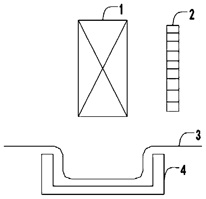
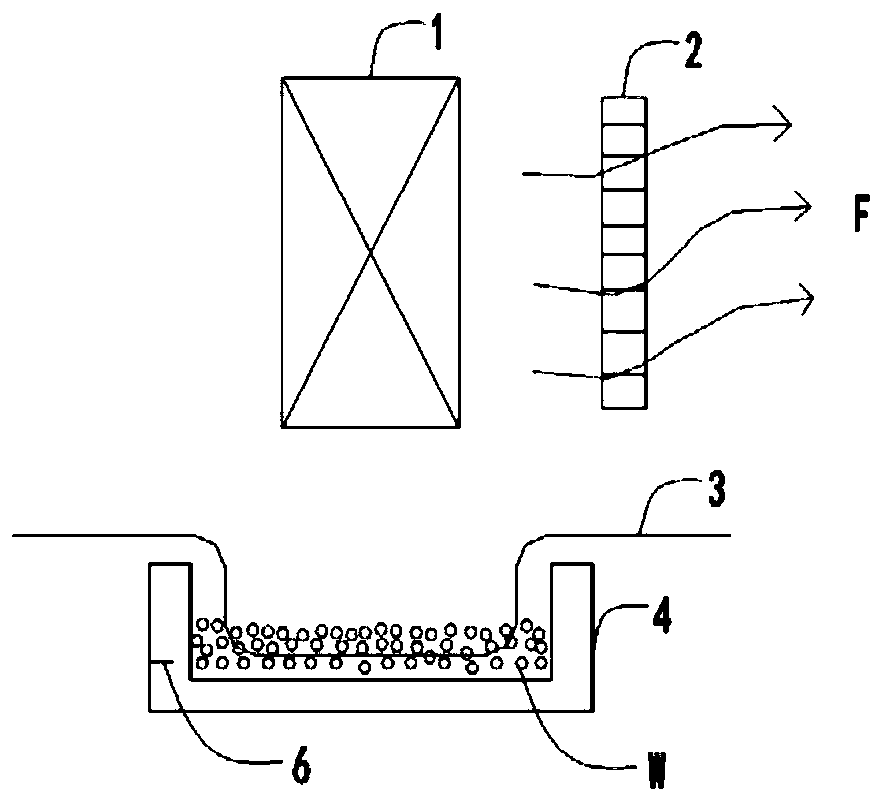
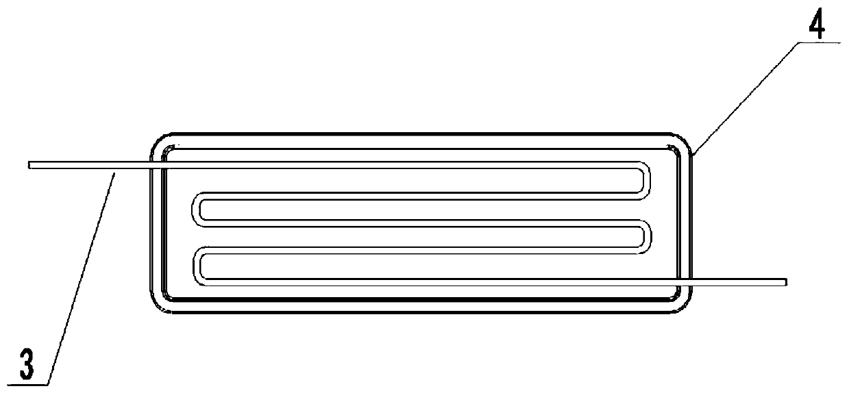
[0037] This embodiment relates to a humidification system, including: a water receiving tray, which is arranged on an air supply flow path below the indoor heat exchanger of the heat pump air conditioner, and the air supply power of the air supply flow path comes from the air supply fan of the indoor heat exchanger. When the indoor unit of the heat pump air conditioner is in cooling operation, the condensed water generated by the indoor heat exchanger is collected into the water receiving pan, and the condensed water in the water receiving pan is continuously evaporated in the air supply flow path. Take it away and send it out through the air outlet of the air conditioner. The humidification system also includes a heat exchange tube that is thermally coupled with the water tray. The heat exchange tube is led from the heat pump air conditioner indoor unit. When the air conditioner indoor mechanism heats up, the...


PUM


Abstract

The invention discloses a humidifying system. The system comprises a water receiving disc which is mounted on an air supply flow path below an indoor heat exchanger of a heat pump air conditioner, airsupply power of the air supply flow path comes from an air supply fan in the indoor heat exchanger, when a heat pump air conditioner indoor unit carries out refrigeration running, condensate water generated by the indoor heat exchanger is collected into the water receiving disc, the condensate water in the water receiving disc is continuously evaporated in the air supply flow path, atomized steamgenerated by evaporation is brought away by the airflow of the air supply flow path to be jointly delivered out through an air conditioner air supply opening, and a room can be humidified. The humanbody comfort can be improved, a human body respiratory system and health can be protected, meanwhile, due to the water receiving disc, and the humidifying function of the humidifying system, the function of an air conditioner water draining pipe can be completely or partly replaced, the condensate water during refrigeration of the air conditioner can be completely or partly drained to the outsidewithout passing through the air conditioner water draining pipe, and the problems that after the air conditioner water draining pipe is used for a long time, due to damage or improper mounting, waterleakage is caused, and finally, the wall is corroded by the condensate water can be solved.

Description

technical field [0001] The invention relates to a humidification system, an air conditioner with the same and a humidification method for controlling it. Specifically, the invention belongs to the technical field of refrigeration equipment. Background technique [0002] With the development of science and technology and the continuous improvement of people's living standards, air-conditioning products have become a must-have product for families. When the air conditioner is in the cooling mode, the water vapor in the room will liquefy into water when it meets the cold evaporator, commonly known as: condensed water, and the condensed water will be discharged to the outside through the drain pipe of the air conditioner's internal unit. On the one hand: when the condensed water is discharged, the humidity in the room will become lower and lower, and the air will become drier, which will greatly affect the comfort of the air in the room and the human respiratory system, especial...

Claims


Application Information

Patent Timeline
Patent Type & Authority Applications(China)
IPC IPC(8): F24F1/0087F24F1/0063F24F13/22F24F13/30F24F11/89F24F11/64F24F110/20
CPCF24F1/0087F24F1/0063F24F13/222F24F13/30F24F11/89F24F11/0008F24F11/64F24F2110/20
Inventor 刘安平方淼陈晓东杨鹏远
Owner GREE ELECTRIC APPLIANCES INC
Why Eureka
Try Eureka