Oxygen-enrich gas water heater and work method thereof

A gas water heater and water heater technology, applied in water heaters, fluid heaters, oxidized water/sewage treatment, etc., can solve the problem of low user experience and achieve the effect of easy selection

Pending Publication Date: 2020-05-08
HANGZHOU DE&E ELECTRICAL CO LTD
View PDF1 Cites 2 Cited by
  • Summary
  • Abstract
  • Description
  • Claims
  • Application Information

AI Technical Summary

Problems solved by technology

[0003] However, the existing gas instant water heater is only used as a water heating device, and for consumers, they hope to obtain a better bathing experience, so only heating the bathing water cannot bring consumers a higher bathing experience. and the pursuit of

Method used


Image

  • Oxygen-enrich gas water heater and work method thereof
  • Oxygen-enrich gas water heater and work method thereof
  • Oxygen-enrich gas water heater and work method thereof

Examples


Embodiment 1

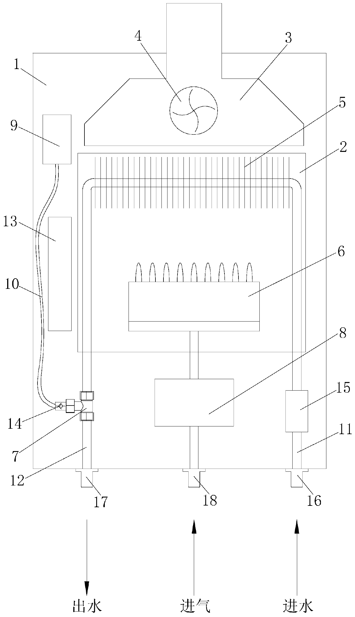
[0045] Example 1 (eg figure 1 , 5 -8 shown).

[0046]The oxygen-enriched gas water heater in this embodiment includes a water heater shell 1, a combustion chamber 2, a smoke collecting hood 3, a fan 4, a heat exchanger 5, a burner 6, a tee joint 7, a gas proportional valve 8, an air pump 9, Inflatable pipe 10, water inlet pipe 11, water outlet pipe 12, controller 13, check valve 14 and water flow sensor 15.

[0047] The combustion chamber 2, the smoke collection hood 3 and the air pump 9 in this embodiment are all located in the water heater shell 1, the smoke collection hood 3 is located above the combustion chamber 2, the fan 4 cooperates with the smoke collection hood 3, the heat exchanger 5 and the combustion chamber The burners 6 are all located in the combustion chamber 2, the burner 6 is connected to the gas proportional valve 8, the air pump 9, the water inlet pipe 11 and the water outlet pipe 12 are all connected to the three-way joint 7, and the water flow sensor 1...

Embodiment 2

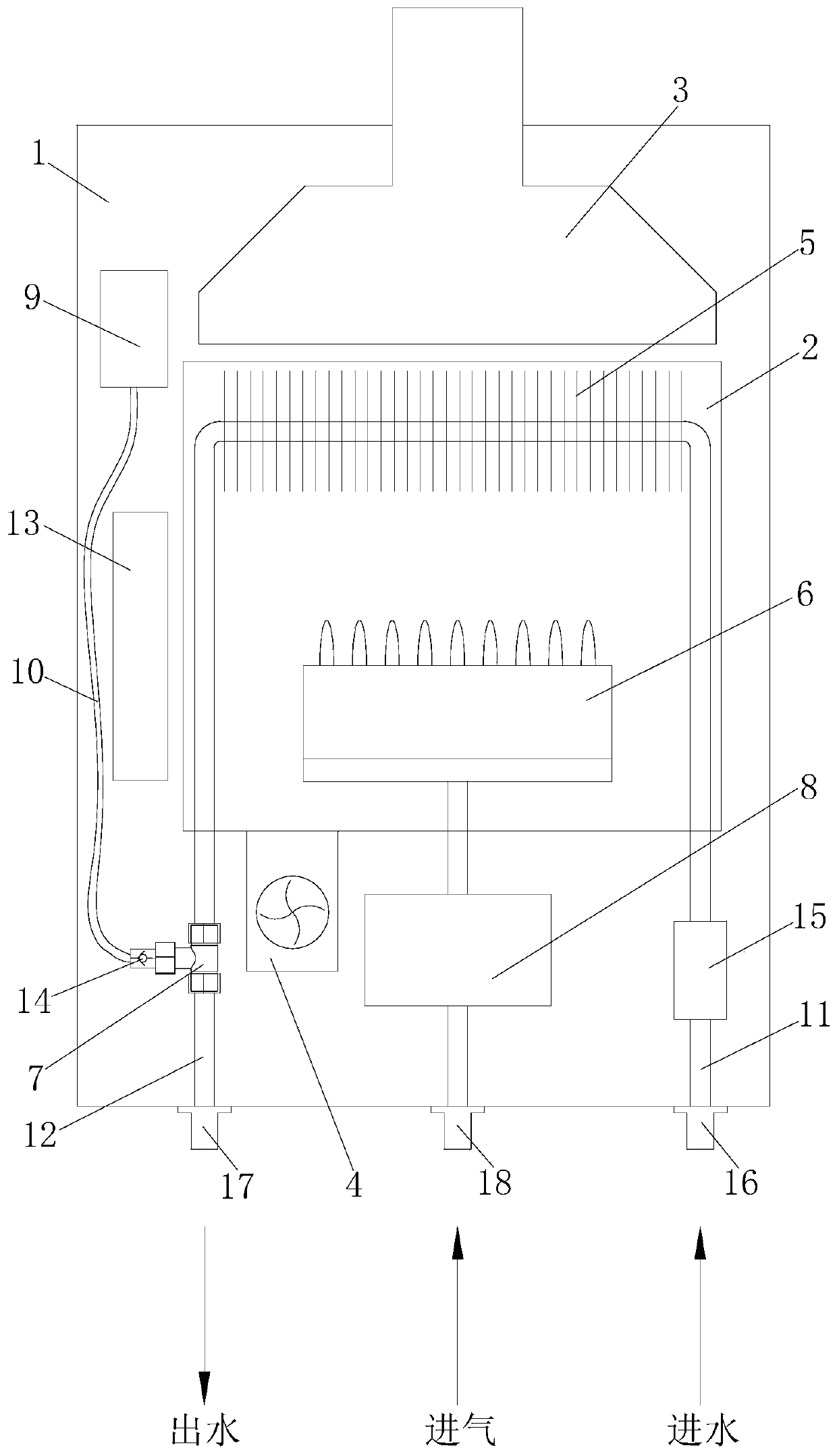
[0059] Example 2 (eg figure 2 , 5 -8 shown).

[0060] The oxygen-enriched gas water heater in this embodiment includes a water heater shell 1, a combustion chamber 2, a smoke collecting hood 3, a fan 4, a heat exchanger 5, a burner 6, a tee joint 7, a gas proportional valve 8, an air pump 9, Inflatable pipe 10, water inlet pipe 11, water outlet pipe 12, controller 13, check valve 14 and water flow sensor 15.

[0061] The combustion chamber 2, the smoke collection hood 3 and the air pump 9 in this embodiment are all located in the water heater shell 1, the smoke collection hood 3 is located above the combustion chamber 2, the fan 4 cooperates with the smoke collection hood 3, the heat exchanger 5 and the combustion chamber The burners 6 are all located in the combustion chamber 2, the burner 6 is connected to the gas proportional valve 8, the air pump 9, the water inlet pipe 11 and the water outlet pipe 12 are all connected to the three-way joint 7, and the water flow sensor...

Embodiment 3

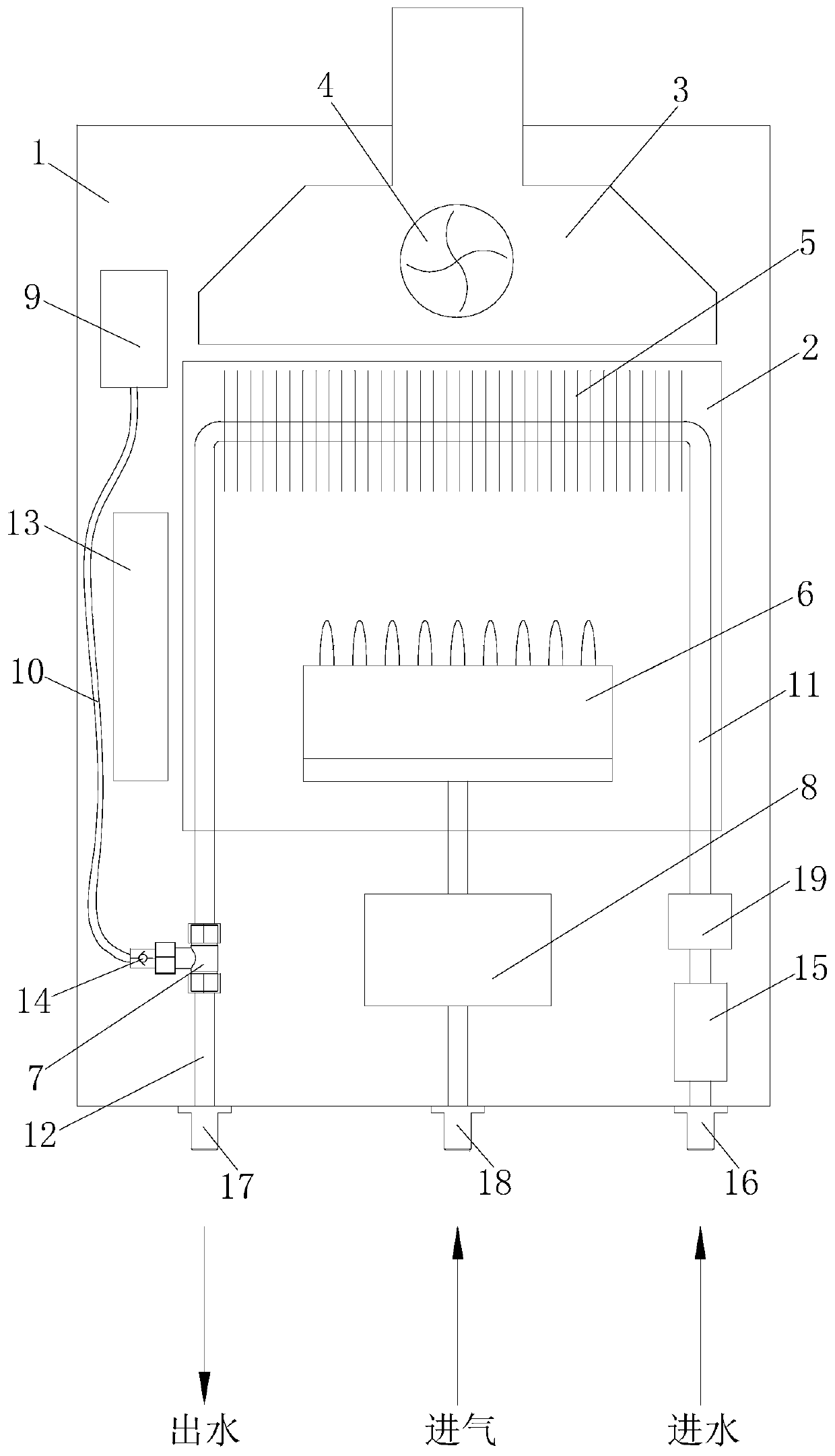
[0073] Example 3 (as image 3 , 5 -8 shown).

[0074] The oxygen-enriched gas water heater in this embodiment includes a water heater shell 1, a combustion chamber 2, a smoke collecting hood 3, a fan 4, a heat exchanger 5, a burner 6, a tee joint 7, a gas proportional valve 8, an air pump 9, Inflatable pipe 10, water inlet pipe 11, water outlet pipe 12, controller 13, check valve 14 and water flow sensor 15.

[0075] The combustion chamber 2, the smoke collection hood 3 and the air pump 9 in this embodiment are all located in the water heater shell 1, the smoke collection hood 3 is located above the combustion chamber 2, the fan 4 cooperates with the smoke collection hood 3, the heat exchanger 5 and the combustion chamber The burners 6 are all located in the combustion chamber 2, the burner 6 is connected to the gas proportional valve 8, the air pump 9, the water inlet pipe 11 and the water outlet pipe 12 are all connected to the three-way joint 7, and the water flow sensor ...


PUM


Abstract

The invention relates to an oxygen-enrich gas water heater and a work method thereof and belongs to the field of water heaters. The oxygen-enrich gas water heater comprises a water heater shell and isstructurally characterized by further comprising a combustion chamber, a smoke collection hood, a draught fan, a heat exchanger, a combustor, a three-way connector, a gas proportional valve, an inflation pump, a water inlet pipe, a water outlet pipe and a water flow sensor; the combustion chamber, the smoke collection hood and the inflation pump are located in the water heater shell; the smoke collection hood is located above the combustion chamber; the draught fan is matched with the smoke collection hood; the heat exchanger and the combustor are located in the combustion chamber; the combustor is connected with the gas proportional valve; the inflation pump, the water inlet pipe and the water outlet pipe are connected with the three-way connector; the water flow sensor is installed on the water inlet pipe; and the water inlet pipe is matched with the heat exchanger. Impacts to the body are reduced, meanwhile, air is charged so that the water amount body sense can be improved, and the bathing experience is improved greatly.

Description

technical field [0001] The invention relates to an oxygen-enriched gas water heater and a working method thereof, belonging to the field of water heaters. Background technique [0002] With the continuous improvement of people's pursuit of quality of life, the requirements for the experience of using hot water are also continuously improved, and the gas instant water heater is also continuously improved and developed under this background. Gas instant water heaters are favored by more and more consumers for their convenient use, large amount of hot water production, and constant temperature. [0003] However, the existing gas instant water heater is only used as a water heating device, and for consumers, they hope to obtain a better bathing experience, so only heating the bathing water cannot bring consumers a higher bathing experience. And the pursuit of bathing comfort has also become a trend to improve the bathing experience. The gas water heater in the prior art has le...

Claims


Application Information

Patent Timeline
IPC IPC(8): F24H1/10F24H9/00F24H9/18F24H9/20C02F1/74F16L41/02
CPCF24H1/107F24H9/0005F24H9/1836F24H9/2035C02F1/74F16L41/021
Inventor 刘远庆刘韬高德康
Owner HANGZHOU DE&E ELECTRICAL CO LTD
Why Eureka
Try Eureka