Non-dispersive water flow path simulation method based on DEM and flow collection

A simulation method and non-dispersive technology, applied in CAD numerical modeling, design optimization/simulation, etc., can solve problems such as difficult to achieve optimal water flow path

Active Publication Date: 2020-05-08
HOHAI UNIV
View PDF5 Cites 2 Cited by
  • Summary
  • Abstract
  • Description
  • Claims
  • Application Information

AI Technical Summary

Problems solved by technology

[0004] Orlandini et al. (2003) proposed a D8-LTD algorithm, which adjusts the Dinf flow direction to one of the 8 directions, and transfers the deviation between the Dinf flow direction and the final direction to the downstream, assisting the local flow direction correction pr

Method used


Image

  • Non-dispersive water flow path simulation method based on DEM and flow collection
  • Non-dispersive water flow path simulation method based on DEM and flow collection
  • Non-dispersive water flow path simulation method based on DEM and flow collection

Examples


Embodiment 1

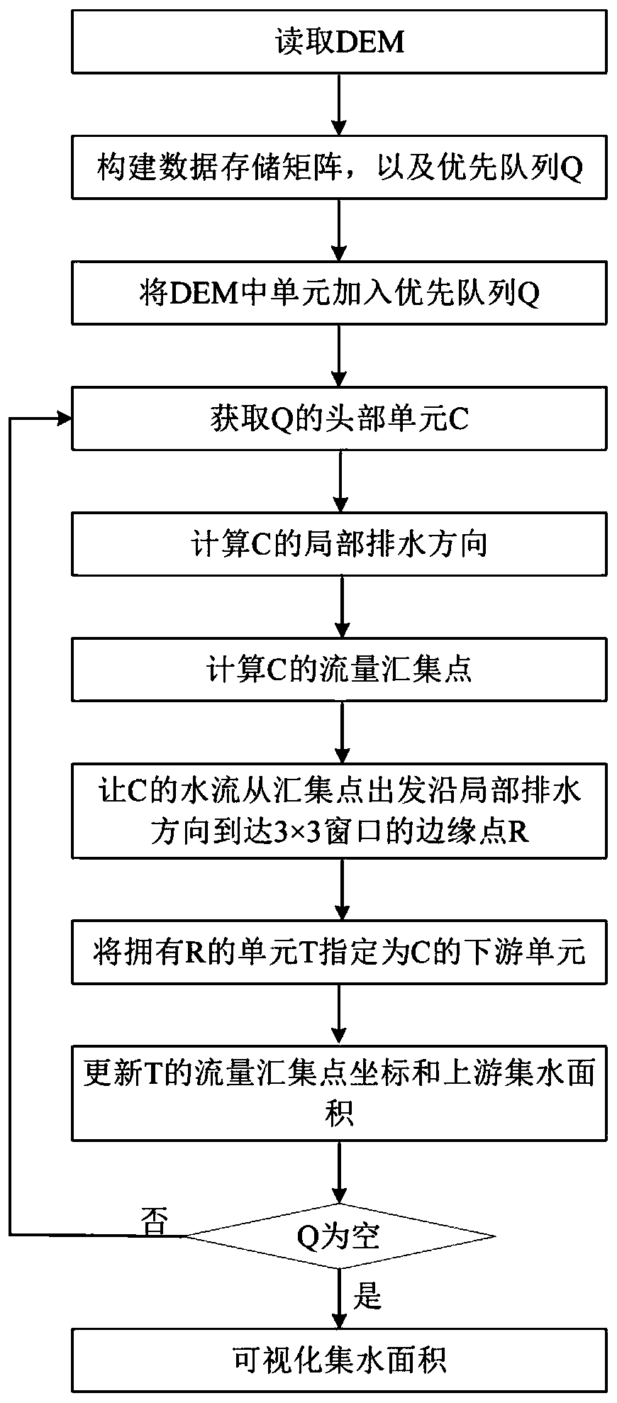
[0083] see Figure 1 to Figure 7 , the technical solution provided by the present invention is, in order to better realize the above-mentioned purpose of the invention, the present invention also provides a non-dispersive water flow path simulation method based on DEM and flow collection, wherein, the specific steps of the method are as follows:

[0084] Step S1. Load the DEM elevation data, read the DEM data as a two-dimensional array A, and create four arrays M, N, L, and S with the same number of rows and columns as A, where M and N are used to store the data of each grid respectively The abscissa X of the relative coordinates between the water flow collection point and the center point, the coordinate value of the ordinate Y, L is used to record the upstream catchment area of ​​each unit, S is used to record the direction of the center point of the downstream unit, M, N, All values ​​in the first column, last column, first row, and last row in L and S are assigned invalid ...

specific example 1

[0116] by Figure 5 Take the 5×5 DEM as an example. In this example, the invalid value is set to -9999, and the local drainage direction is provided by the Dinf method. The processing flow and results are as follows Image 6 shown; the specific steps are as follows:

[0117] Step S1, read the DEM data as an array A (Figure (6a)), create an array M ( Image 6 (d)), N( Image 6 (e)), L( Image 6 (f)), S( Image 6 (g)), assign invalid values ​​to the first column, last column, first row, and last row in M, N, L, and S, and create a priority queue Q sorted by unit from high to low ( Image 6 (b));

[0118] Step S2, except the first column, the last column, the first row, and the last row, scan the remaining cells in the array A, and judge whether each cell of the array A is an invalid value -9999, and this step does not find an invalid value cell, Then determine whether there are invalid value units in the 8 adjacent units around the unit. Here, unit B4 in A is found to be ...

specific example 2

[0126] by Figure 7 (a), Figure 7 Take the plane and concave DEM in (b) as an example, the size of the two DEMs is 51×51, the elevation distribution has been marked in the figure, and the traditional D8 method, D8-LTD method and the present invention are used to obtain the two surfaces respectively The non-diffusion flow path of , the visualized flow path is as Figure 7 (c)-7(h), Figure 7 The black line in the figure is the water flow path, and the gray line is the contour line. The ideal water flow path should flow perpendicular to the contour line. It can be found that the water flow path obtained by the D8 method is very straight and not perpendicular to the contour line ( Figure 7 (c), 7(d)), although D8-LTD is well applied on a plane, the water flow path can be roughly perpendicular to the contour line ( Figure 7 (e)), but the water flow path obtained by this method on the concave surface has a phenomenon of disordered crossing ( Figure 7 (f)), the present inven...


PUM


Abstract

The invention provides a non-dispersive water flow path simulation method based on DEM and flow collection, and belongs to the technical field of digital terrain analysis. According to the technical scheme, the method comprises the steps of gradually determining the position of a flow collection point of each grid from high to low according to the elevation, simulating the process that the flow flows from the collection points in the local drainage direction, determining a downstream unit of each DEM grid unit, and finally connecting out a non-dispersive water flow path. The method has the beneficial effect that the method for better simulating the flowing process of the water flow on the earth surface is provided for the DEM-based hydrological model.

Description

technical field [0001] The invention relates to the technical field of digital terrain analysis, in particular to a non-dispersive water flow path simulation method based on DEM and flow collection. Background technique [0002] The water flow path refers to the flow trajectory of water on the surface due to gravity. Most of the current distributed hydrological models use the water flow path to estimate the flow distance of water flow from the point of generation to the outlet of the river channel or basin, and then obtain model parameters such as hillside width and confluence time. . Since the current hydrological models mostly use grid-type digital elevation models (Digital Elevation Model, DEM) to describe the surface terrain, the digital water flow paths are also mostly extracted based on DEM. At present, there are two types of water flow path extraction algorithms based on DEM, namely diffuse type and non-dispersive type. Among them, the dispersion algorithm believes ...

Claims


Application Information

Patent Timeline
IPC IPC(8): G06F30/20G06F111/10
Inventor 吴鹏飞刘金涛姚杰夫费俊源刘杨洋
Owner HOHAI UNIV
Why Eureka
Try Eureka