Check patentability & draft patents in minutes with Patsnap Eureka AI!

Auxiliary heat transfer structure of memory

A memory and auxiliary heat technology, applied in electric solid state devices, semiconductor devices, semiconductor/solid state device parts, etc. Good abrasiveness, wear resistance and thermal conductivity

Pending Publication Date: 2020-05-08
ASIA VITAL COMPONENTS (CHINA) CO LTD
View PDF0 Cites 0 Cited by
  • Summary
  • Abstract
  • Description
  • Claims
  • Application Information

AI Technical Summary

Problems solved by technology

[0002] There are many electronic chips used for data calculation in the current electronic equipment, and these electronic chips are the heating elements that generate heat in the electronic equipment. Traditionally, heat-generating elements are dissipated through heat transfer elements (heat pipes, uniform temperature, etc.) plate, heat sink, etc.) directly contact the heat source and correspondingly set up a cooling fan to force the heat dissipation of the heat fransfer element, but with the advancement of electronic chips with stronger computing power, the heat generated is also increased a lot, so the traditional antipyretic The method can no longer be satisfied, and it is necessary to dissipate heat by water cooling
[0003] Water cooling mainly performs heat exchange by setting water-cooling pipelines in electronic equipment and cold heads used for heat absorption, but one of the heat sources (memory units) in electronic equipment has multiple chips on the surface, and these chips must be directly Attach the water-cooling head component or water-cooling kit that absorbs the heat source for cooling. Once the water-cooling kit is assembled, it is difficult to rework it. Generally, users cannot replace internal damaged electronic components such as memory units, so the entire set must be replaced. After the electronic equipment is returned to the original factory, the original factory will replace the memory unit and other electronic components, which is quite inconvenient
[0004] In addition, when the outer shell (that is, metal or ceramic material) of the memory chip package is in contact with the outer surface of the water cooling kit, friction is often generated due to plugging and unplugging, and scratches are easily generated on the outer shell surface of the memory chip package to form thermal resistance. Phenomenon or damage to the external shell to expose the memory chip and be polluted
[0005] In addition, when the surface of the water-cooling kit pipeline is rubbed against the outer casing of the memory chip package, the water-cooling kit pipeline is prone to damage, which will cause water leakage and short-circuit damage to the memory. The above-mentioned problems will be caused by friction at any time and need to be improved

Method used


Image

  • Auxiliary heat transfer structure of memory
  • Auxiliary heat transfer structure of memory
  • Auxiliary heat transfer structure of memory

Examples


Embodiment Construction

[0026] The above-mentioned purpose of the present invention and its structural and functional characteristics will be described according to the preferred embodiments of the accompanying drawings.

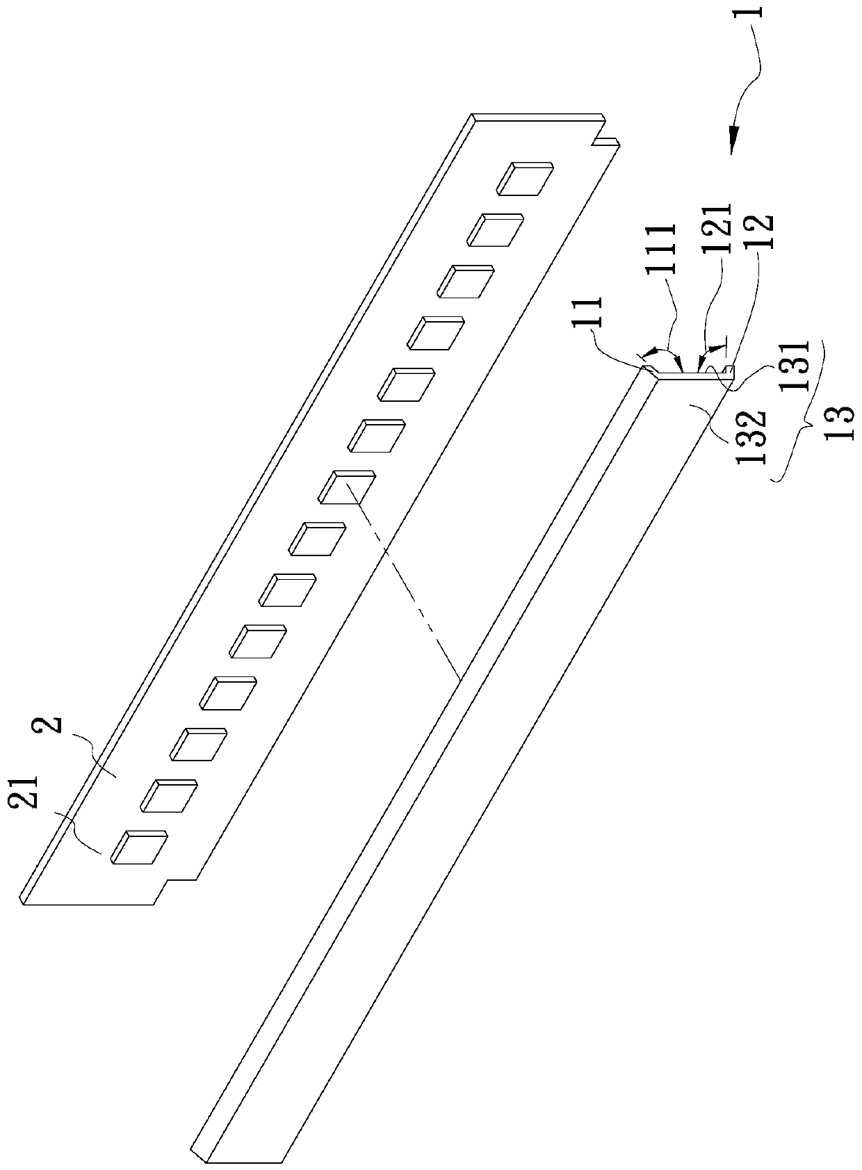
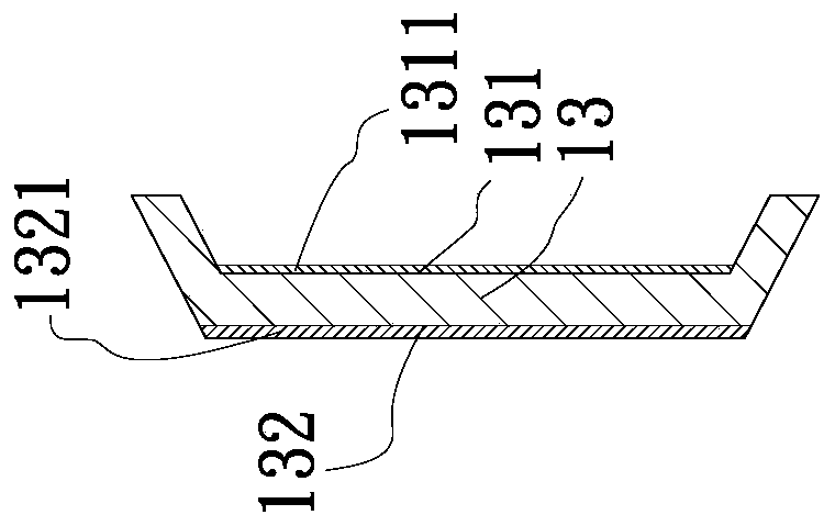
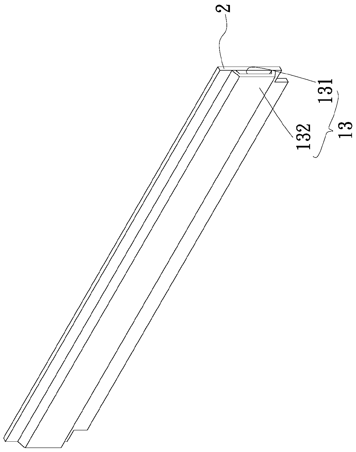
[0027] see figure 1 , Figure 1a , figure 2 , is a three-dimensional exploded, cross-sectional and combined view of the first embodiment of the memory-assisted heat transfer structure of the present invention. As shown in the figure, the memory-assisted heat transfer structure of the present invention is combined with at least one memory unit and a water-cooling component correspondingly It is assumed that the memory auxiliary heat transfer structure includes: a body 1;

[0028] The main body 1 has a first end 11, a second end 12 and an intermediate section 13. 1. There may be an included angle or a curved surface or an arc surface between the two ends 11 and 12, wherein the included angle is a first included angle 111 and a second included angle 121, and the first and second i...


PUM


Abstract

The invention provides an auxiliary heat transfer structure of a memory. The structure is correspondingly assembled with at least one memory unit and a water cooling assembly. The structure comprisesa body which is provided with a first end, a second end and a middle section, wherein the middle section is provided with a heated side and a contact side, the heated side is arranged corresponding toat least one chip arranged on the memory body unit, and the contact side is assembled with the water cooling assembly in an attached mode. By means of the structure, the friction between the memory body unit and the water cooling assembly can be reduced, gaps can be filled, and the thermal resistance phenomenon can be reduced.

Description

technical field [0001] The invention relates to a memory auxiliary heat transfer structure, in particular to a memory auxiliary heat transfer structure which is wear-resistant and has a high heat transfer coefficient and can reduce thermal impedance. Background technique [0002] There are many electronic chips used for data calculation in the current electronic equipment, and these electronic chips are the heating elements that generate heat in the electronic equipment. Traditionally, heat-generating elements are dissipated through heat transfer elements (heat pipes, uniform temperature, etc.) plate, heat sink, etc.) directly contact the heat source and correspondingly set up a cooling fan to force the heat dissipation of the heat fransfer element, but with the advancement of electronic chips with stronger computing power, the heat generated is also increased a lot, so the traditional antipyretic The method can no longer be satisfied, and it is necessary to dissipate heat t...

Claims


Application Information

Patent Timeline
Patent Type & Authority Applications(China)
IPC IPC(8): H01L23/473
CPCH01L23/473
Inventor 李嵩蔚
Owner ASIA VITAL COMPONENTS (CHINA) CO LTD
Features
  • R&D
  • Intellectual Property
  • Life Sciences
  • Materials
  • Tech Scout
  • Unparalleled Data Quality
  • Higher Quality Content
  • 60% Fewer Hallucinations
Learn More