Heat exchanger

A technology of heat exchangers and oxides, applied in the direction of heat exchange equipment, indirect heat exchangers, heat exchanger types, etc., can solve problems such as unsuitable heat exchangers, and achieve the effect of maintaining antibacterial function

Pending Publication Date: 2020-05-08
LG ELECTRONICS INC
View PDF5 Cites 0 Cited by
  • Summary
  • Abstract
  • Description
  • Claims
  • Application Information

AI Technical Summary

Problems solved by technology

[0007] Therefore, there is a limitation that said

Method used


Image

  • Heat exchanger
  • Heat exchanger
  • Heat exchanger

Examples


Embodiment Construction

[0032] Hereinafter, the heat exchanger according to the present invention will be described in more detail with reference to the drawings. Expressions of singular number used in the present invention shall include expressions of plural number unless a different meaning is clearly indicated in the context.

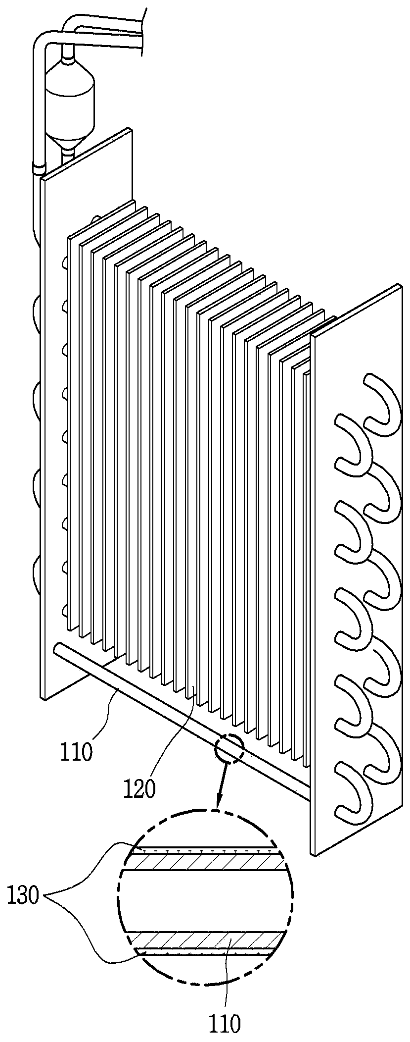
[0033] figure 1 It is a conceptual diagram showing an example of the heat exchanger provided by this invention.

[0034] The refrigerant tube 110 forms a flow path of a heat exchange fluid. The heat exchange fluid may be, for example, a refrigerant. The refrigerant pipe may pass through the cooling fins in a straight line, change directions outside the cooling fins, and repeatedly pass through the cooling fins again.

[0035] The cooling fins 120 are used to increase the heat exchange efficiency of the heat exchanger by expanding the heat exchange area. The cooling fins are coupled to the refrigerant tubes. if refer to figure 1 , shows that the cooling fins are formed...


PUM

PropertyMeasurementUnit
The average thicknessaaaaaaaaaa
Average sizeaaaaaaaaaa

Abstract

A heat exchanger of the present invention is operated in a cooling operation mode in which a region to be heat-exchanged is cooled by the heat exchanger or in a drying operation mode in which the heatexchanger is supplied with wind from a blowing fan, and comprises: a refrigerant pipe which forms a flow path of a refrigerant; a cooling fin which is coupled to the refrigerant pipe; and a hydrophilic coating with which the surface of at least one of the refrigerant pipe and the cooling fin is coated, wherein the hydrophilic coating contains: a first type transition metal oxide which becomes acidic by reacting with water formed on the refrigerant pipe or the cooling fin, so as to have antimicrobial activity when the heat exchanger is operated in the cooling operation mode; and a second typetransition metal oxide or a post transition metal oxide which has antimicrobial activity when the heat exchanger is operated in the drying operation mode.

Description

technical field [0001] The present invention relates to a heat exchanger with antibacterial and deodorizing functional surfaces. Background technique [0002] Heat exchangers are used in various technical fields such as air conditioners and refrigerators. However, in the case of continuous operation of the heat exchanger, moisture will condense on the surface of the heat exchanger. For example, when a heat exchanger is used as an indoor unit (evaporator) of an air conditioner, the temperature of the indoor unit becomes lower than normal temperature when the air conditioner performs a cooling operation. As a result, condensed water condenses on the surface of the indoor unit. [0003] Condensate that condenses on the heat exchanger surfaces can cause bacterial growth. This is because bacteria thrive in damp places. In addition, bacteria such as mold and the like can cause unpleasant odors. In order to solve the above-mentioned problems, it may be considered to immediatel...

Claims


Application Information

Patent Timeline
IPC IPC(8): F28F21/08F28F19/04F28F19/06F24F13/30
CPCF28F19/04F28F19/06F28F21/08F28F1/32F28D1/0477F28D2021/0085F28D2021/0071F28F2265/20F28F2245/00C09K3/18F24F1/0059F28F2245/02F24F1/0067F24F13/22F24F2013/221A61L2/232A61L9/01C09D5/084C09D129/04C09D133/02C09D139/06C09D167/04F28F13/182
Inventor 金芝现金烔汉吴超姬李瑞真秦台圭洪尚炫
Owner LG ELECTRONICS INC
Why Eureka
Try Eureka