
Welding method of tube plate butt structure and welding system

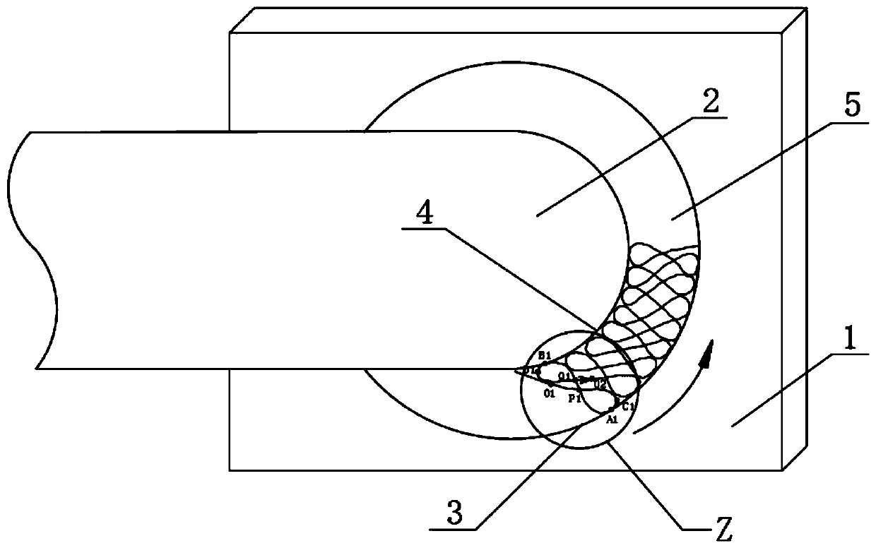
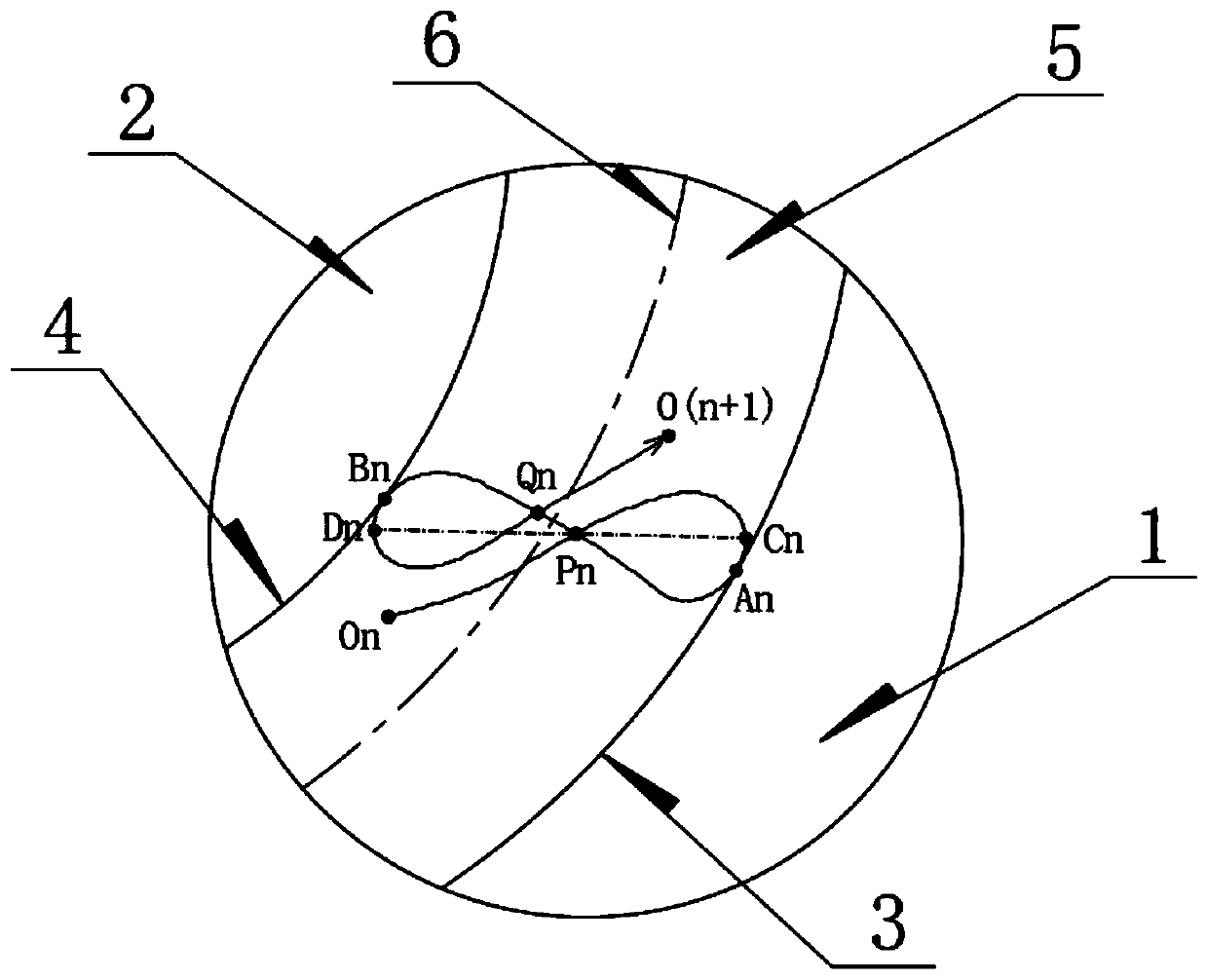
A welding method and tube sheet technology, applied in welding equipment, welding accessories, arc welding equipment, etc., can solve problems such as poor forming, back weld formation and adverse effects of weld surface formation, and solve the problems of molten pool dripping, heating Large contact area and arc dwell time, realize the effect of continuous and uninterrupted welding in all positions

Active Publication Date: 2020-05-12
CRRC QINGDAO SIFANG CO LTD
View PDF6 Cites 2 Cited by
  • Summary
  • Abstract
  • Description
  • Claims
  • Application Information

AI Technical Summary

Problems solved by technology

[0010] The embodiment of the present invention provides a welding method and a welding system for a tube-sheet butt joint structure, which is used to solve the problem that the welding method and welding system in the prior art are affected by external forces during the welding process due to the weld droplet transition at different welding positions. , it is prone to various types of bad forming, which will cause adverse effects on the back weld formation and weld surface formation.

Method used


Image

  • Welding method of tube plate butt structure and welding system
  • Welding method of tube plate butt structure and welding system
  • Welding method of tube plate butt structure and welding system

Examples


Embodiment Construction

[0032] Embodiments of the present invention will be further described in detail below in conjunction with the accompanying drawings and examples. The following examples are used to illustrate the present invention, but should not be used to limit the scope of the present invention.

[0033] In the description of the present invention, unless otherwise specified, the meanings of "plurality" and "several" both refer to two or more than two. The orientation or positional relationship indicated by the terms "upper", "lower", "left", "right", "inner", "outer", "front end", "rear end", "head", "tail" etc. is Based on the orientation or positional relationship shown in the drawings, it is only for the convenience of describing the present invention and simplifying the description, and does not indicate or imply that the referred device or element must have a specific orientation, be constructed and operated in a specific orientation, and therefore cannot be understood To limit the p...


PUM


Abstract

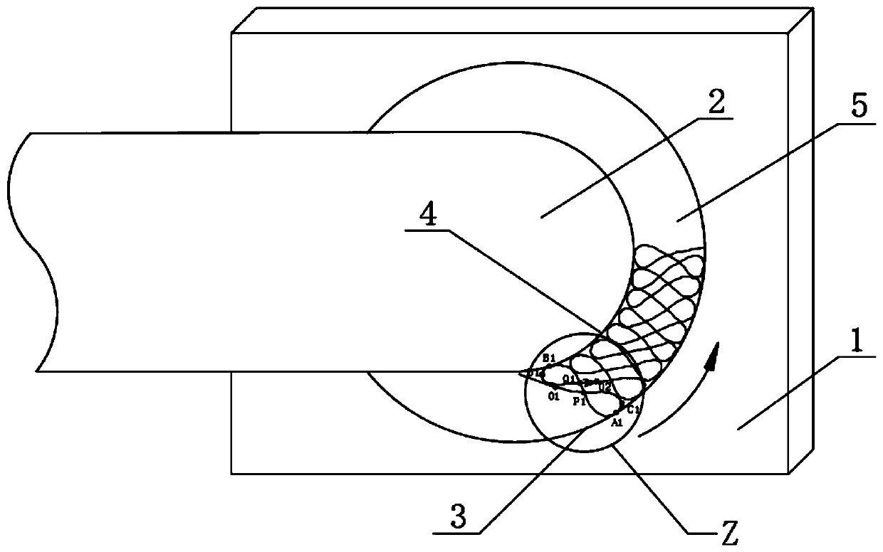
The invention belongs to the technical field of welding, and particularly relates to a welding method of a tube plate butt structure and a welding system. The welding method includes the steps that awelding gun is driven to continuously weld in a circumferential weld of the tube plate butt structure along the circumferential weld, and the welding gun is driven to move in a multi-crossing mode between the groove side and the non-groove side of the circumferential weld according to an electrode manipulation route during the continuous welding process. According to the welding method, the movingroute of the welding gun is used to realize the "stacked figure 8-shaped" electrode manipulation route, so that the contact area between molten pool metal and a base metal and the retention time of electric arcs in the circumferential weld are increased, the defect of downward-dripping of the molten metal in the weld due to the influence of gravity is overcome, and the electric arc heat input canbe reasonably distributed according to the structural characteristics of the groove side and the non-groove side, so that the problems of molten pool dripping, insufficient or excessive penetration and poor weld forming which are prone to occurring in the all-position welding of the tube plate butt structure are fundamentally solved; and all-position continuous and uninterrupted welding of the tube plate butt structure can be achieved.

Description

technical field [0001] The invention relates to the field of welding technology, in particular to a welding method and a welding system for a tube-sheet butt joint structure. Background technique [0002] The locomotive bogie frame is mostly made of medium-thick plate (thickness more than 8mm) beveled and welded. MAG welding refers to molten active gas shielded arc welding, and MAG welding is often used in the welding of frame structures to weld frames. Due to the actual situation of the frame structure, space location and technological equipment, there is a welding structure in which the pipe and the plate are butt jointed (referred to as the tube-sheet butt joint structure) during welding. Welding in the flat welding position, so fixed all-position welding must be used. [0003] The weld seams of fixed all-position welding include at least PE position, PD position, PF position, PB position, PA position and other welding positions, and different welding positions need to ...

Claims


Application Information

Patent Timeline
Patent Type & Authority Applications(China)
IPC IPC(8): B23K9/173B23K9/12B23K9/32
CPCB23K9/12B23K9/125B23K9/173B23K9/32
Inventor 郭文俊徐西振陶有朋吴向阳王宝昌
Owner CRRC QINGDAO SIFANG CO LTD
Learn More