Water cooling type iron storage type iron runner structure

An iron ditch and iron storage technology, applied in cooling devices, discharge devices, etc., can solve problems such as inability to implement and explode, and achieve the effect of increasing service life

Pending Publication Date: 2020-05-12
REWELL REFRACTORY ZHENGZHOU CO LTD
View PDF6 Cites 1 Cited by
  • Summary
  • Abstract
  • Description
  • Claims
  • Application Information

AI Technical Summary

Problems solved by technology

Once the water cooling device leaks, the water will explode after entering the iron gutter. Because the safety problem can...

Method used


Image

  • Water cooling type iron storage type iron runner structure
  • Water cooling type iron storage type iron runner structure
  • Water cooling type iron storage type iron runner structure

Examples


Embodiment Construction

[0019] The technical solution of the present invention will be described in more detail below through specific embodiments, so as to facilitate the understanding of those skilled in the art.

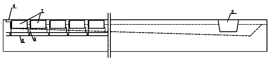
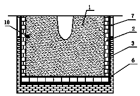
[0020] Such as figure 1 , figure 2 As shown, the water-cooled iron storage type iron gutter structure described in the present invention includes a working layer 1 that is in direct contact with the high-temperature mixed solution, and a permanent layer 2 and a steel shell 3 that are coated outside the working layer 1; in order to achieve a good Heat conduction effect, the present invention uses carbon composite bricks (heat conduction at room temperature ≥ 13 W / m·K, compressive strength ≥ 45MPa) to build the permanent layer; the steel shell between the iron tap hole 4 and the skimmer 5 A water cooling device is installed on the outer wall. In order to achieve a good cooling effect, a water cooling device can be installed outside the steel shell between the taphole 4 and the skimmer 5....


PUM


Abstract

The invention discloses a water cooling type iron storage type iron runner structure which comprises a working layer, a permanent layer and a steel shell. The working layer makes direct contact with ahigh temperature mixed solution. The permanent layer coats the working layer. The permanent layer is formed by building carbon composite bricks. A water cooling device is arranged at the portion, corresponding to the height of an iron runner groove, of the outer side wall of the steel shell. The water cooling device is arranged at the outer attached wall of the steel shell. High-alumina castableor high-aluminum bricks for traditional iron storage type iron runner permanent layers are changed into carbon composite brick building with the good heat conducting performance, cooling water flowingin inner circulation of the water cooling device is used for driving away abundant heat of the iron runner, the temperature inside the iron runner is kept constant, and the permeation, abrasion, erosion and other damage effects influenced by iron scraps on a linear of the iron runner are kept within the reasonable range. Meanwhile, the water cooling device is installed at the outer side of the iron runner steel shell, even if water leakage is caused, water cannot enter the iron runner, and therefore it is ensured that water cannot meet water, and security water cooling is achieved.

Description

technical field [0001] The invention relates to an iron gutter for an ironmaking blast furnace, in particular to a water-cooled iron storage type iron gutter structure. Background technique [0002] The iron ditch is an important facility for the production of ironmaking blast furnaces. It is the carrier for the separation of slag and iron after the high-temperature molten iron flows out of the blast furnace, and it is also the channel for the high-temperature molten iron to flow to molten iron containers such as molten iron tanks. [0003] What flows out of the blast furnace is a high-temperature liquid mixed with slag and molten iron, and the slag content in the high-temperature liquid accounts for about one-third. The length of the iron ditch of the blast furnace is about 10-15 meters. When the high-temperature mixed solution passes through the iron storage ditch, the specific gravity of the molten iron is large and will remain in the lower part of the ditch. The slag wil...

Claims


Application Information

Patent Timeline
IPC IPC(8): C21B7/14C21B7/10
CPCC21B7/14C21B7/10
Inventor 丁丰收孙龙豹贺晓杰晁尚奎
Owner REWELL REFRACTORY ZHENGZHOU CO LTD
Why Eureka
Try Eureka