Float removing device used for water treatment

A technology for cleaning devices and floating objects, which is applied in the fields of cleaning open water, grain processing, water conservancy projects, etc., which can solve problems such as low efficiency, and achieve the effect of improving efficiency and optimizing water quality

Inactive Publication Date: 2020-05-12
CHENGDU HENGLIDA TECH
View PDF7 Cites 7 Cited by
  • Summary
  • Abstract
  • Description
  • Claims
  • Application Information

AI Technical Summary

Problems solved by technology

[0003] The purpose of the present invention is to solve the shortcomings of low efficiency in cleaning the floating objects in the water body existing in the prior art, and propose a floating object cleaning device for water treatment, including a shell, a buoy, a crushing device and a tank. One end of the shell is provided with a first channel communicating with the box, the other end of the shell is provided with a second channel communicating with the box, and one end of the shell with the first channel is also provided with a crushing device. The device includes a first motor, a cutting knife and a crushing knife arranged on the housing, and a vertical crushing knife is arranged under the horizontal cutting knife; a driving device is installed in the second channel, and the driving device pushes the floating objects for water treatment When the cleaning device moves in the water, negative pressure can be generated inside the tank and in the first channel, and the floating matter pulverized by the crushing device can be sucked into the tank. In the box, and collected through the box, it can clean up various floating objects in the water body, optimize the water quality, and improve the efficiency of water body cleaning

Method used


Image

  • Float removing device used for water treatment
  • Float removing device used for water treatment
  • Float removing device used for water treatment

Examples


Embodiment Construction

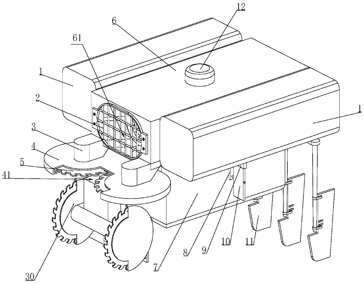
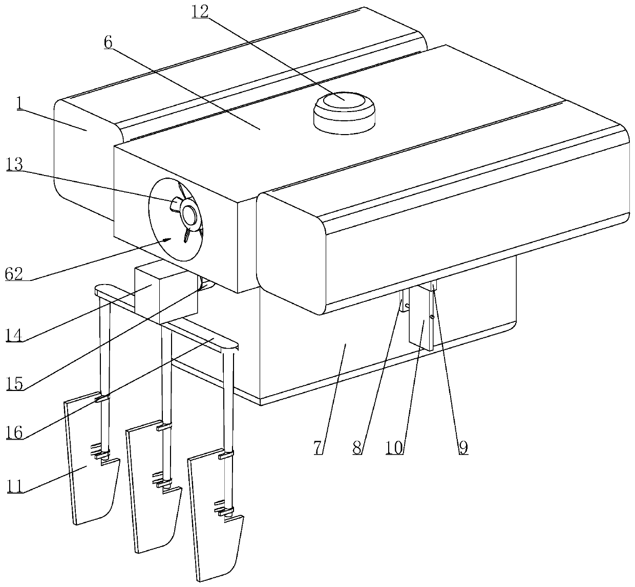
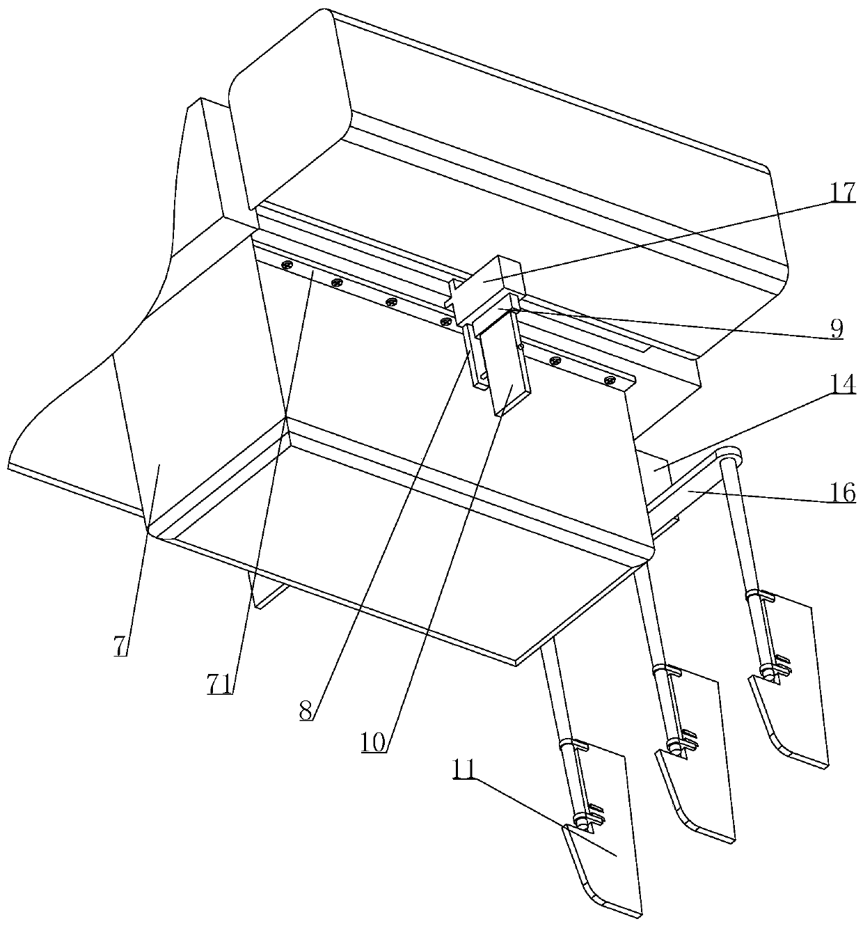
[0029] Please refer to Figure 1-6 , a device for clearing floating objects for water treatment, comprising a housing 6, buoys 1 arranged on the left and right sides of the housing 6, a crushing device, and a box 7 connected to the bottom end of the housing 6, the One end of the housing 6 is provided with a first channel communicating with one end inside the box 7, and the other end of the housing 6 is provided with a second channel communicating with the other end inside the box 7. The device is installed in the first passage, and a driving device is installed in the second passage. When the driving device pushes the floating object cleaning device for water treatment to move in the water, it can make the inside of the box 7 and the Negative pressure is generated in the first channel, and the floating matter crushed by the crushing device is sucked into the box body 7 .

[0030] A crushing device is also provided at one end of the housing 6 where the first passage is opened,...


PUM


Abstract

The invention relates to the field of environment-friendly equipment and particularly discloses a float removing device used for water treatment. The float removing device comprises a shell, a floating cylinder, a smashing device and a box body. A first channel communicating with the interior of the box body is arranged at one end of the shell, and a second channel communicating with the interiorof the box body is arranged at the other end of the shell. A breaking device is further arranged at the end, provided with the first channel, of the shell. The breaking device comprises a first motor,a cutting tool and a breaking tool which are arranged on the shell. The vertical breaking tool is arranged below the cutting tool which is transversely arranged. A drive device is arranged in the second channel, and when the drive device pushes the float removing device used for water treatment to move in water, negative pressure can be generated in the box body and in the first channel, and floats smashed by the smashing device are sucked into the box body. By means of the float removing device used for water treatment, in the moving process, the floats in water are sucked into the shell andthe box body and are collected through the box body, various floats in water can be removed, the water quality is optimized, and the water body cleaning efficiency is improved.

Description

technical field [0001] The invention relates to the technical field of environmental protection equipment, in particular to a floating object cleaning device for water treatment. Background technique [0002] For the treatment of water pollution, aquatic plants are often used now. The leaves of aquatic plants are soft and transparent, and some form filaments, such as hornwort. Filamentous leaves can greatly increase the contact area with water, making the leaves in the water to maximize photosynthesis. However, due to the eutrophication of the water body, when the sewage is purified by planting aquatic plants, the growth of aquatic plants sometimes becomes uncontrollable. At the same time, after the water body is polluted, it will also cause other aquatic plants to grow too densely, causing the surface of the water body to be messy and affecting the water quality, such as the outbreak of blue-green algae. Further, floating garbage in the water body, including acids, alkali...

Claims


Application Information

Patent Timeline
Patent Type & Authority Applications(China)
IPC IPC(8): E02B15/10B02C18/14
CPCB02C18/14E02B15/10
Inventor 徐自强
Owner CHENGDU HENGLIDA TECH
Why Eureka
Try Eureka