A high energy density energy storage and release system and energy storage and release method

A technology with high energy density and energy release, applied in the direction of liquid variable displacement machinery, liquid fuel engine, machine/engine, etc., can solve the problems of high water storage site selection requirements, low operating efficiency, etc., and achieve the requirement of no geographical difference , high operating efficiency, ensuring the effect of water flow

Active Publication Date: 2021-11-19
XI AN JIAOTONG UNIV
View PDF4 Cites 0 Cited by
  • Summary
  • Abstract
  • Description
  • Claims
  • Application Information

AI Technical Summary

Problems solved by technology

[0005] The purpose of the present invention is to provide a high energy density energy storage and release system and energy storage and release method to overcome the problems of low operating efficiency and high requirements for water storage site selection in the prior art. The present invention can use water pumps and water turbines to achieve pressure The storage and release of potential energy can effectively avoid the irreversible loss of the system and improve the operating efficiency of the system

Method used


Image

  • A high energy density energy storage and release system and energy storage and release method
  • A high energy density energy storage and release system and energy storage and release method

Examples


Embodiment Construction

[0030] The present invention is described in further detail below in conjunction with accompanying drawing:

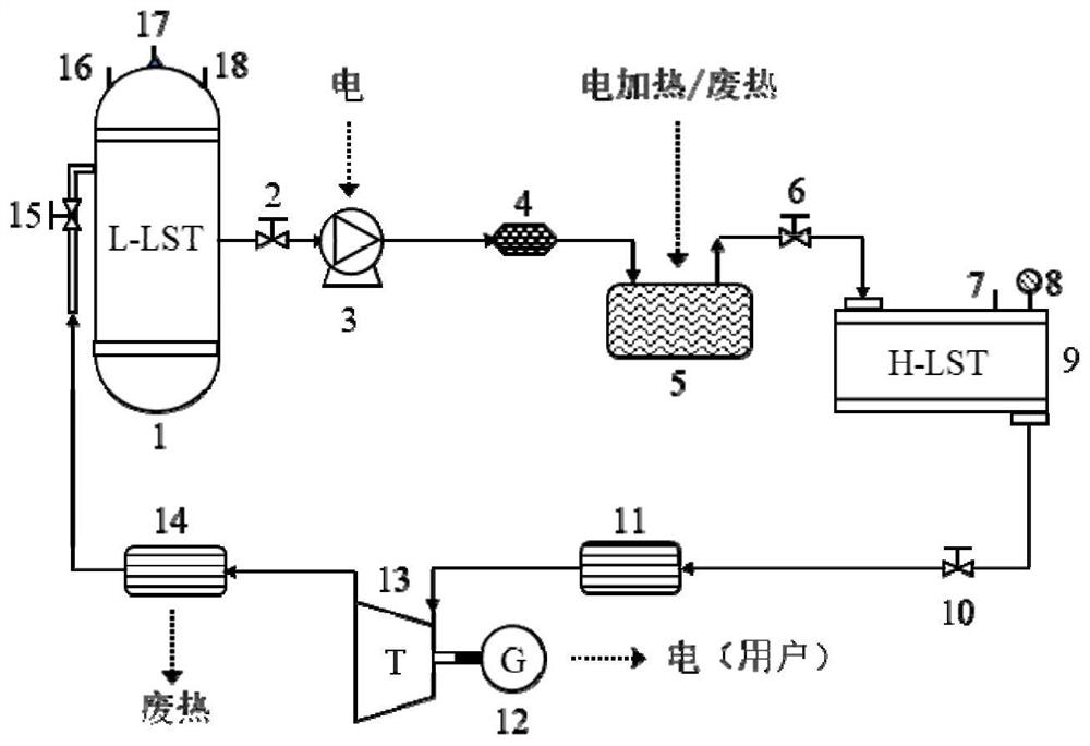
[0031] Such as figure 1 , figure 2 As shown, a high energy density energy storage and release system includes a normal temperature water storage tank 1, a high temperature and high pressure water storage tank 9, a reheater 11 and a cooler 14, the water outlet of the normal temperature water storage tank 1 and the high temperature and high pressure water storage tank 9 water inlets are connected in turn with a booster pump unit 3 and a heater 5, the water outlet of the high-temperature and high-pressure water storage tank 9 is connected to the water inlet of the reheater 11, and the gas outlet of the reheater 11 is connected to a high-pressure steam turbine 13 The high-pressure steam turbine 13 is connected to the generator 12, the outlet of the high-pressure steam turbine 13 is connected to the inlet of the cooler 14, and the liquid outlet of the cooler 14 is connect...


PUM


Abstract

The invention discloses a high-energy-density energy storage and release system and an energy storage and release method. The water after a booster pump unit passes through a heater is heated and pressurized and stored in a high-temperature and high-pressure water storage tank to form high-temperature and high-pressure water quality storage potential energy. When electric energy is needed, the high-temperature and high-pressure working medium in the high-temperature and high-pressure water storage tank is directly reheated through the reheater to form completely saturated superheated steam, and the fully saturated superheated steam expands into wet saturated steam in the high-pressure steam turbine to store high-temperature and high-pressure water The working fluid coming out of the tank can be simply heated to meet the maximum steam energy recovery requirements, and then the waste heat that flows into the cooler is recovered and cooled, and then returned to the normal temperature water storage tank, thus forming a closed-loop energy storage and release system, only one high-temperature and high-pressure water storage tank is required For energy storage, the structure is simple, and it can ensure the use of normal temperature water storage tanks for storage of working fluids, without geographical potential difference requirements, and the use of high temperature and high pressure water vapor mixed storage, high operating efficiency, and high recovery efficiency in the process of potential energy.

Description

technical field [0001] The invention relates to the technical field of physical energy storage, in particular to a high-energy-density energy storage and release system and an energy storage and release method. Background technique [0002] In order to solve the problem of large-scale grid-connection of intermittent renewable energy and improve the efficiency, safety, and economy of grid operation, the development of large-scale electric energy storage technology has become the focus of common attention of domestic and foreign researchers. As a transitional technology of the power system, energy storage technology can store the electric energy generated by renewable energy when the power load is low, and then output it in a certain way when the energy is needed by the outside world, which can cut peaks and fill valleys for the power grid. It can effectively alleviate the instability of power load and improve the grid-connected utilization rate of renewable energy power gener...

Claims


Application Information

Patent Timeline
Patent Type & Authority Patents(China)
IPC IPC(8): F01K13/00F01D15/10F04B17/03F04B23/02F04B23/04F04B53/08
CPCF01D15/10F01K13/006F04B17/03F04B23/02F04B23/04F04B53/08
Inventor 李瑞雄王焕然姚尔人陈昊张严严凯
Owner XI AN JIAOTONG UNIV
Why Eureka
Try Eureka