Fuel cell metal bipolar plate and fuel cell

A metal bipolar plate and fuel cell technology, applied in fuel cells, fuel cell components, circuits, etc., can solve the problems that the supply rate cannot match the hydrogen supply rate, reduce the output performance of fuel cells, and uneven gas distribution, etc. Achieve the effects of improving power generation efficiency and output performance, preventing local overheating, and improving output performance

Pending Publication Date: 2020-05-12
GREE ELECTRIC APPLIANCES INC
View PDF0 Cites 8 Cited by
  • Summary
  • Abstract
  • Description
  • Claims
  • Application Information

AI Technical Summary

Problems solved by technology

[0005] In a hydrogen-oxygen fuel cell, oxygen flows on the cathode plate, and hydrogen flows on the anode plate. Since the diffusion rate of hydrogen is much greater than that of oxygen (about 4 times that of oxygen), and the demand for hydrogen is higher than that of oxygen The demand for hydrogen is less, the rate of hydrogen diffusion to the anode catalytic layer through the flow channel on the anode plate is faster than the rate of oxygen diffusion to the cathode catalytic layer through the flow channel on the cathode plate, and due to the flow field structure of the cathode plate and the anode plate Similarly, the supply rate of oxygen cannot match the supply rate of hydrogen, so that part of the hydrogen that has entered fails to participate in the reaction, resulting in uneven gas distribution and insufficient reaction, thereby reducing the output performance of the fuel cell

Method used


Image

  • Fuel cell metal bipolar plate and fuel cell
  • Fuel cell metal bipolar plate and fuel cell
  • Fuel cell metal bipolar plate and fuel cell

Examples


Embodiment 1

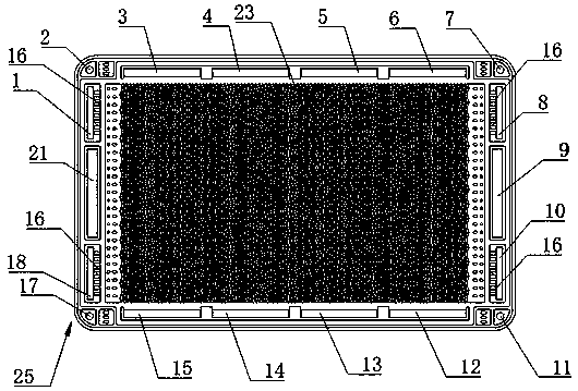
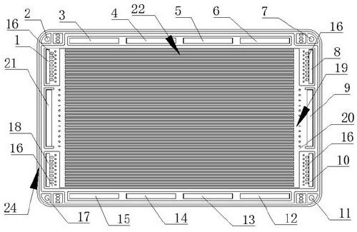
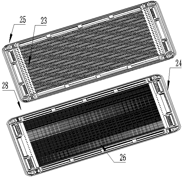
[0038] see Figure 1-4 As shown, the fuel cell metal bipolar plate of the present invention includes a cathode plate 25 , an anode plate 24 and a coolant flow field 28 formed between the cathode plate 25 and the anode plate 24 . Wherein, a plurality of parallel wave-shaped flow channels 23 are arranged in the middle of the cathode plate 25 , and a plurality of parallel straight-flow channels 22 are arranged in the middle of the anode plate 24 .

[0039] see figure 1 and figure 2As shown, the cathode plate 25 and the anode plate 24 are rectangular structures, wherein, the wave-shaped flow channel 23 on the cathode plate 25 is arranged along the width direction of the cathode plate 25, and the direct flow channel on the anode plate 24 22 is arranged along the length direction of the anode plate 24 . Its purpose is that the flow field structure of the cathode plate 25 produces water during operation, and by allowing the wave-shaped flow channel 23 to be arranged along the wid...

Embodiment 2

[0048] The difference between this embodiment and embodiment 1 is that the positions of air inlets 3, 4, 5, 6 and air outlets 12, 13, 14, 15 in embodiment 1 are exchanged in this embodiment, and the hydrogen inlet 9 The positions of the hydrogen outlet and the hydrogen outlet 21 are exchanged, and the positions of the coolant inlets 1, 18 and the coolant outlets 8, 10 are exchanged.

[0049] In this embodiment, other implementations other than the above are carried out with reference to Embodiment 1.

Embodiment 3

[0051] The difference between this embodiment and Embodiment 1 is that in this embodiment, the wave-shaped flow channel and the straight channel are arranged along the length direction of the cathode plate and the anode plate.

[0052] In this embodiment, other implementations other than the above are carried out with reference to Embodiment 1.


PUM


Abstract

The invention discloses a fuel cell metal bipolar plate and a fuel cell. The bipolar plate comprises a cathode plate (25), an anode plate (24) and a cooling liquid flow field (28) formed between the cathode plate (25) and the anode plate (24); a plurality of parallel wavy flow channels (23) are arranged in the middle of the cathode plate (25), and a plurality of parallel straight flow channels (22) are arranged in the middle of the anode plate (24). According to the metal bipolar plate of the fuel cell, reaction gas can uniformly flow in a flow field, so the reaction is sufficient, and the output performance of the fuel cell is further improved.

Description

technical field [0001] The invention relates to a fuel cell, in particular to a fuel cell metal bipolar plate and a fuel cell comprising the bipolar plate. Background technique [0002] As the core component of the fuel cell, the bipolar plate not only has the functions of collecting current and supporting the membrane electrode, but also evenly distributes the reaction gas. The metal bipolar plate is generally processed by welding two metal veneers, and the metal veneer is formed by stamping a stainless steel sheet, and there is a flow area formed by the combination of gas flow channels on it. A coolant flow space is formed. [0003] The two plates are composed of an anode plate and a cathode plate. The anode plate is provided with a fuel flow area, and the fuel diffuses to the anode catalytic layer through the flow channel; the cathode plate is provided with an oxidant flow area, and the oxidant diffuses to the cathode through the flow channel. catalytic layer. [0004]...

Claims


Application Information

Patent Timeline
Patent Type & Authority Applications(China)
IPC IPC(8): H01M8/026H01M8/0263H01M8/0267
CPCH01M8/026H01M8/0263H01M8/0267Y02E60/50
Inventor 张永魏宇鸿肖彪张威
Owner GREE ELECTRIC APPLIANCES INC
Why Eureka
Try Eureka