Tripping mechanism and surge protector adopting tripping mechanism

A tripping mechanism and tripping technology, applied in emergency protection circuit devices for limiting overcurrent/overvoltage, emergency protection devices for automatic disconnection, emergency protection circuit devices, etc., can solve the reliability of surge protectors And problems such as low safety, unstable state of varistor deterioration, difficult circuit protection devices, etc., to achieve simple and reliable structure, improve sensitivity, and ensure safety

Pending Publication Date: 2020-05-12
天津市中力防雷技术有限公司
View PDF0 Cites 3 Cited by
  • Summary
  • Abstract
  • Description
  • Claims
  • Application Information

AI Technical Summary

Problems solved by technology

[0005] However, there are the following defects in the prior art: First, in the above-mentioned first method, the action of the thermal tripping device is based on the response of the low-temperature solder to the temperature, and the low-temperature solder is easily affected by the environment, and its melting point is unstable; and it is restricted by the welding process , there may be a phenomenon that the tripping mechanism cannot be disengaged due to solder adhesion and wire drawing; at the same time, after the low-temperature solder of the thermal tripping device is fused, the surge protector cannot continue to be used, and it needs to be re-soldered or replaced with a new one. The surge protector cannot be reused; secondly, in the second method above, taking the circuit breaker as an exam

Method used


Image

  • Tripping mechanism and surge protector adopting tripping mechanism
  • Tripping mechanism and surge protector adopting tripping mechanism
  • Tripping mechanism and surge protector adopting tripping mechanism

Examples


Embodiment 1

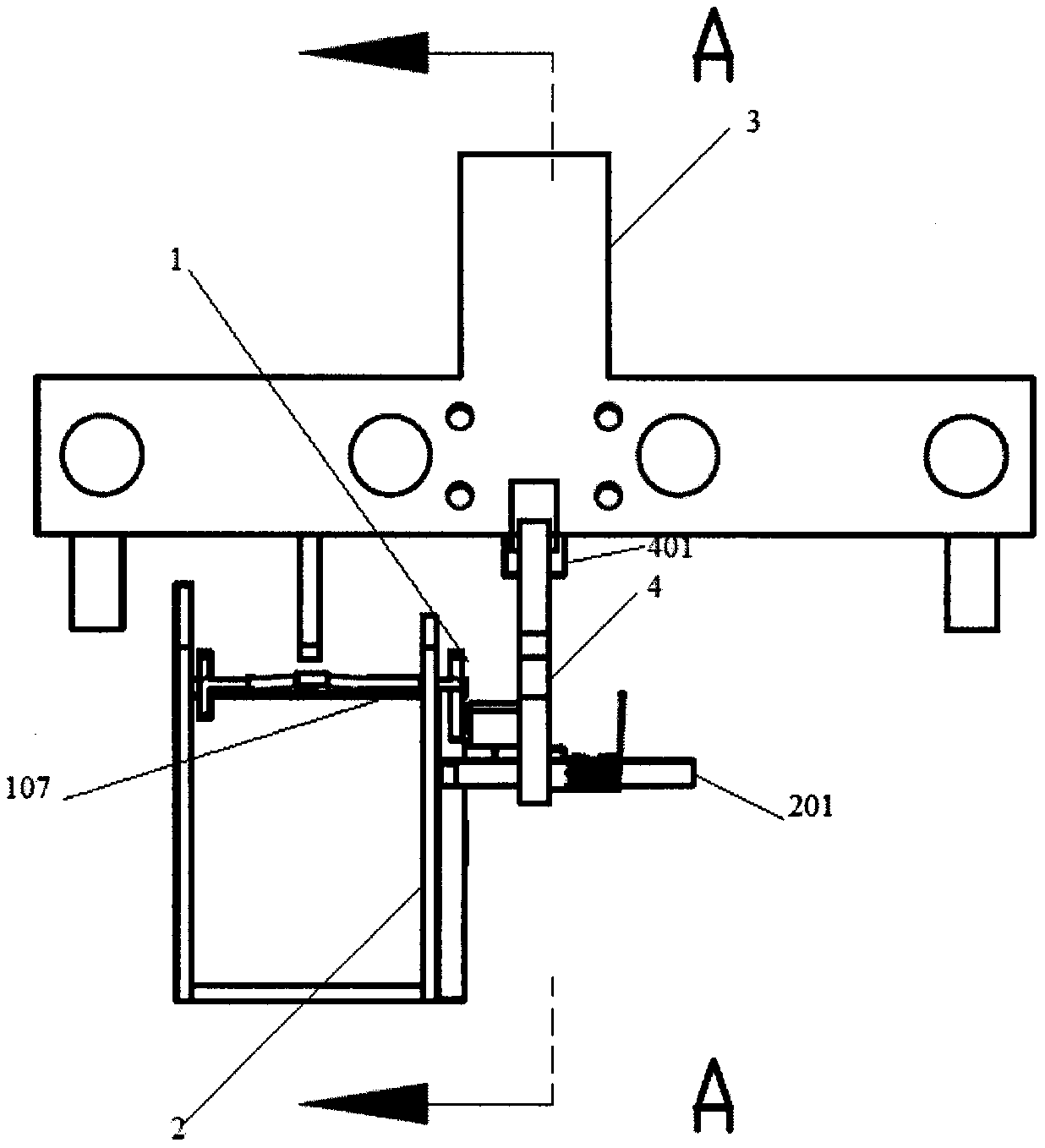
[0078] figure 1 Schematic diagram of the structure of the tripping mechanism provided by Embodiment 1 of the present invention; figure 2 for figure 1 The schematic diagram of the A-A section structure; image 3 A schematic diagram of the three-dimensional structure of the tripping mechanism provided by Embodiment 1 of the present invention;

[0079]A tripping mechanism, including a first driving mechanism 1, a guide bracket 2, a movable contact 3 and a tripping piece 4, the first driving mechanism 1 is erected on the guiding bracket 2, the first driving mechanism 1 includes a flip plate 107, and the flip The plate 107 is hinged with the guide bracket 2, and the movable contact 3 is connected with the turning plate 107 by transmission;

[0080] The tripping part 4 includes a hook part 401, a first trigger part 402, a third trigger part 405 and a shaft part 403, the shaft part 403 is connected to the first pole, the second pole, and the third trigger part 405, and the hook p...

Embodiment 2

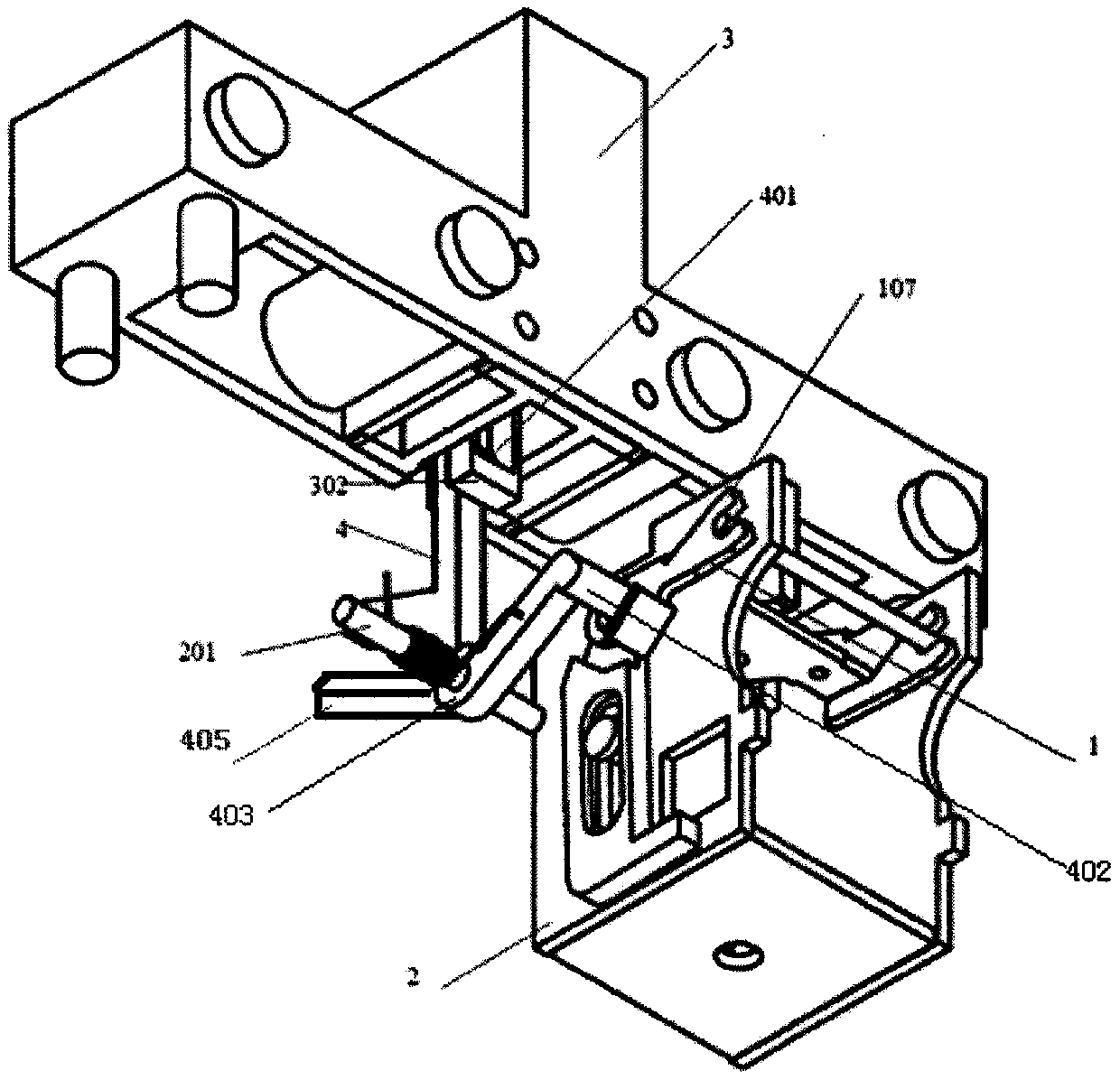
[0087] Figure 4 A schematic diagram of the three-dimensional structure of the tripping mechanism provided by Embodiment 2 of the present invention;

[0088] Except the technical scheme of embodiment 1, also comprise following technical scheme:

[0089] The first driving mechanism 1 also includes a driver 102 and a clamping shaft 103, the driver 102 is arranged on the guide bracket 2, the driver 102 is driven and connected with the turning plate 107, the driver 102 drives the turning plate 107 to rotate, and the clamping shaft 103 is arranged on the guiding bracket 2, The turning plate 107 is movably clamped on the clamping shaft 103 .

[0090] The specific working process of the tripping mechanism is that the initial state is that the hook part 401 of the tripping part 4 and the hanging ring part 302 are in the tripping state, and the circuit is in the disconnected state. When the moving contact 3 is pressed, the moving contact 3 Press down the flap 107, and at the same tim...

Embodiment 3

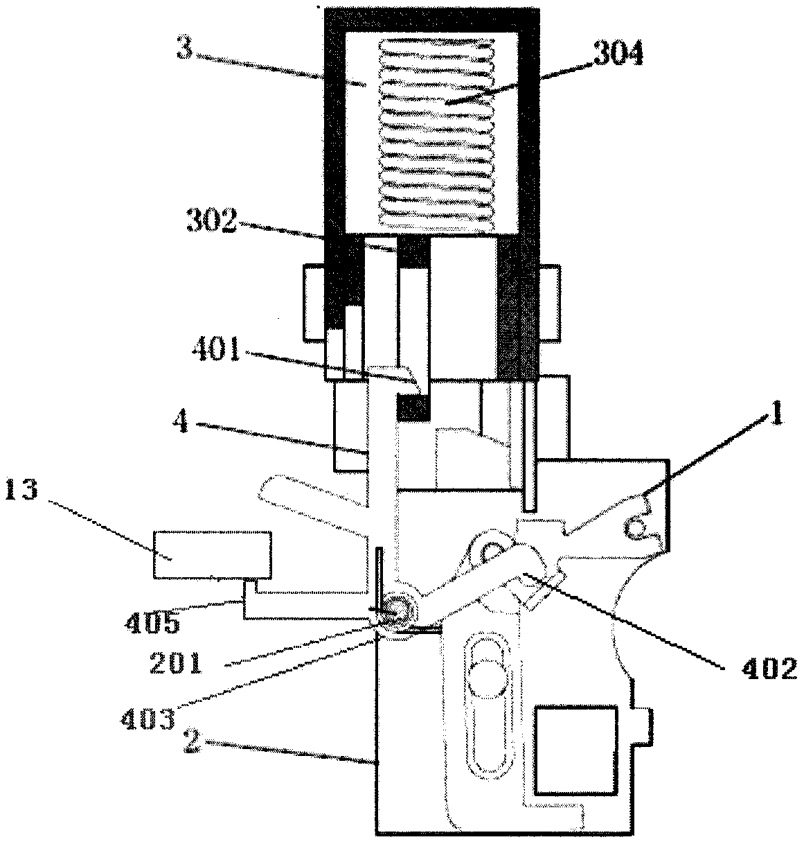
[0093] Figure 5 A partial cross-sectional schematic diagram of the tripping mechanism provided for Embodiment 3 of the present invention; Image 6 A schematic diagram of the three-dimensional structure of the tripping mechanism provided by Embodiment 3 of the present invention;

[0094] Except the technical scheme of embodiment 1, also comprise following technical scheme:

[0095] The turnover plate 107 includes a rotating part 109, a transmission part 110, a guide part 108 and a pushing part 111 connected in sequence. It is movably connected with the guide bracket 2 , and the pushing part 111 is in transmission connection with the tripping part 4 , and the tripping part 4 rotates with the rotation of the pushing part 111 .

[0096] The specific working process of the tripping mechanism is that the initial state is that the hook part 401 of the tripping part 4 and the hanging ring part 302 are in the tripping state, and the circuit is in the disconnected state. When the mov...


PUM


Abstract

The invention provides a tripping mechanism and a surge protector adopting the tripping mechanism. A first driving mechanism is erected on a guide bracket, and the first driving mechanism comprises aturning plate, wherein the turning plate is hinged with the guide bracket, a movable contact part is in transmission connection with the turning plate, and the turning plate is in transmission connection with a tripping part. The surge protector comprises at least one tripping mechanism and further comprises a lightning protection element, a signal detection device and a micro-control unit, and the tripping mechanism is connected to a circuit where the lightning protection element is located in series. According to the scheme, the tripping mechanism is simple and reliable in structure and quick in response; the sensitivity, reliability and stability of switching-on and switching-off actions are obviously improved; the repeated closing and releasing can be realized; the surge protector is simple in structure and convenient to use, improves the use efficiency, has a manual tripping function, meets the requirements of no tripping when lightning current or surge current impact occurs and rapid and accurate tripping when power frequency current, short-circuit current or overload current occurs, improves the reliability and safety of the surge protector, prolongs the service life of thesurge protector, and ensures the safety of a low-voltage distribution line.

Description

technical field [0001] The invention belongs to the technical field of low-voltage power distribution, and in particular relates to a tripping mechanism and a surge protector using the tripping mechanism. Background technique [0002] Surge protector (SPD) Surge protector is a device used for surge protection of power supply and signal equipment, and is an indispensable device in low-voltage power distribution system. [0003] At present, in the low-voltage power distribution environment, the voltage-limiting surge protector is the most commonly used, which uses a varistor with the advantages of fast response, low residual voltage, and strong impact resistance as a lightning protection component. However, due to the defects of varistor characteristics such as easy deterioration, unstable deterioration state, and discontinuous change in resistance value, after multiple lightning strikes or surge shocks, the varistor deteriorates, generates leakage current and generates heat a...

Claims


Application Information

Patent Timeline
IPC IPC(8): H02H3/02H02H1/00H02H9/00H02H9/02H01H23/14H01H23/16H01H23/24
CPCH01H23/14H01H23/16H01H23/24H02H1/0007H02H3/021H02H9/00H02H9/02
Inventor 孙巍巍
Owner 天津市中力防雷技术有限公司
Why Eureka
Try Eureka