Framed plate for electronic equipment and plastic forming method

An electronic equipment, plastic molding technology, applied in the direction of electrical equipment shell/cabinet/drawer, electrical components, chassis/cabinet/drawer parts, etc., can solve the problems of large shrinkage, sheet deformation, etc. The effect of plastic usage, enhancement of mechanical strength, and reduction of sheet deformation

Pending Publication Date: 2020-05-12
合肥山秀碳纤科技有限公司
View PDF0 Cites 0 Cited by
  • Summary
  • Abstract
  • Description
  • Claims
  • Application Information

AI Technical Summary

Problems solved by technology

[0005] The invention provides a framed board for electronic equipment and a plastic molding method, which solves the technical problem that the plastic is directly poured into the edge of the board in the prior art, and the shrinkage of the plastic is large after molding, which easily causes the deformation of the board, and achieves enhanced The mechanical strength of the edge of the plate reduces the amount of plastic used and the technical effect of reducing the deformation of the plate

Method used


Image

  • Framed plate for electronic equipment and plastic forming method
  • Framed plate for electronic equipment and plastic forming method
  • Framed plate for electronic equipment and plastic forming method

Examples


Embodiment 1

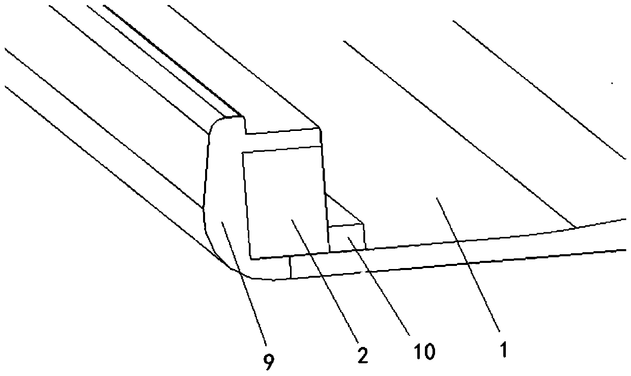
[0031] The embodiment of the present invention provides a framed board for electronic equipment, please refer to the attached Figure 1-2 , used to make housings for electronic devices, the framed sheet includes:

[0032] board body 1;

[0033] Specifically, the board body 1 is a board with a certain shape and a certain shape, and a plurality of the board bodies 1 are assembled together to form a casing, and electronic equipment is arranged in the casing.

[0034] A frame body 2, the frame body 2 is fixed on the edge of the upper surface of the board body 1;

[0035] Further, the frame body includes: a third surface, the third surface is fixed on the upper surface of the board body 1 by pasting to form an overlapping portion, the width of the overlapping portion is K, and the third surface The width of the surface is P; where, 0.5P≤K≤P.

[0036] Specifically, the panel body 1 has an upper surface, a lower surface and side edges, and the upper surface and the lower surface a...

Embodiment 2

[0068] The present application also provides a plastic molding method for making the framed sheet for electronic equipment, please refer to the attached Figure 1-2 , the plastic molding method includes:

[0069] Step 1: paste the frame body 2 on the edge of the upper surface of the board body 1;

[0070] Step 2: Put the board body 1 with the frame body 2 fixed into the mold;

[0071] Step 3: pouring plastic material into the mold to form the first plastic body 9 and the second plastic body 10;

[0072] Step 4: After the plastic material is solidified, remove the mold.

[0073] Further, the mold has at least two injection ports.

[0074] Specifically, the mold includes at least two injection ports, namely a first injection port and a second injection port, and plastic material is poured into the first injection port to form the first plastic body 9; Plastic material is poured into the second injection port to form the second plastic body 10 .

[0075] Through the plastic ...


PUM


Abstract

The embodiment of the invention provides a framed plate for electronic equipment and a plastic molding method. The framed plate is used for manufacturing a shell of an electronic device, and the framed plate comprises a plate body, a frame body and a first plastic body; the frame body is fixed on the edge of the upper surface of the plate body, and the frame body comprises a first edge, a second edge, a first surface, a second surface, M first grooves and N second grooves, wherein the M first grooves are formed in the first edge; the N second grooves are formed in the second edge; the first plastic body wraps the first surface, the second surface and the second edge, fills the first groove and the second groove, and is connected with the side edge of the plate body, wherein M and N are 0 or positive integers. According to the invention, the technical problems that in the prior art, plastic is directly poured into the edge of a plate, the shrinkage amount is large after plastic forming,and plate deformation is likely to be caused are solved, and the technical effects of enhancing the mechanical strength of the edge of the plate, reducing the plastic consumption and reducing the plate deformation degree are achieved.

Description

technical field [0001] The invention relates to the technical field of electronic equipment shells, in particular to a framed plate for electronic equipment and a plastic molding method. Background technique [0002] At present, the housing of an electronic device is usually assembled from a plurality of formed plates. Plastic materials are placed on the edges of the plates by in-mold molding to completely wrap the edges of the plates, which not only increases the airtightness of the shell, but also reduces the The vibration between the plates on the shell reduces the noise of the shell. [0003] However, the inventors of the present application have found that the above-mentioned prior art has at least the following technical problems: [0004] The plastic material is directly wrapped on the edge of the board by in-mold molding. After the plastic material is formed, it shrinks a lot, causing the deformation of the board and making the appearance of the board uneven, thereb...

Claims


Application Information

Patent Timeline
Patent Type & Authority Applications(China)
IPC IPC(8): H05K5/02H05K5/06
CPCH05K5/0217H05K5/06
Inventor 张春笋
Owner 合肥山秀碳纤科技有限公司
Why Eureka
Try Eureka