Porous pig tail catheter device

A catheter device and pigtail technology, applied in the field of medical supplies, can solve the problems of not being able to continuously identify true and false cavities, and achieve the effects of imaging, accurate positioning, and identification

Pending Publication Date: 2020-05-15
范卫东
View PDF0 Cites 2 Cited by
  • Summary
  • Abstract
  • Description
  • Claims
  • Application Information

AI Technical Summary

Problems solved by technology

[0004] In order to overcome the problem that the existing pigtail catheter is used for the treatment of aortic dissection, the guide wire catheter is repeatedly inserted and exited, and the true and false lumen cannot be continuously identified during angiography. The present invention provide

Method used


Image

  • Porous pig tail catheter device
  • Porous pig tail catheter device
  • Porous pig tail catheter device

Examples


Embodiment 1

[0045] Example 1 Porous pigtail catheter device

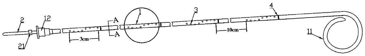
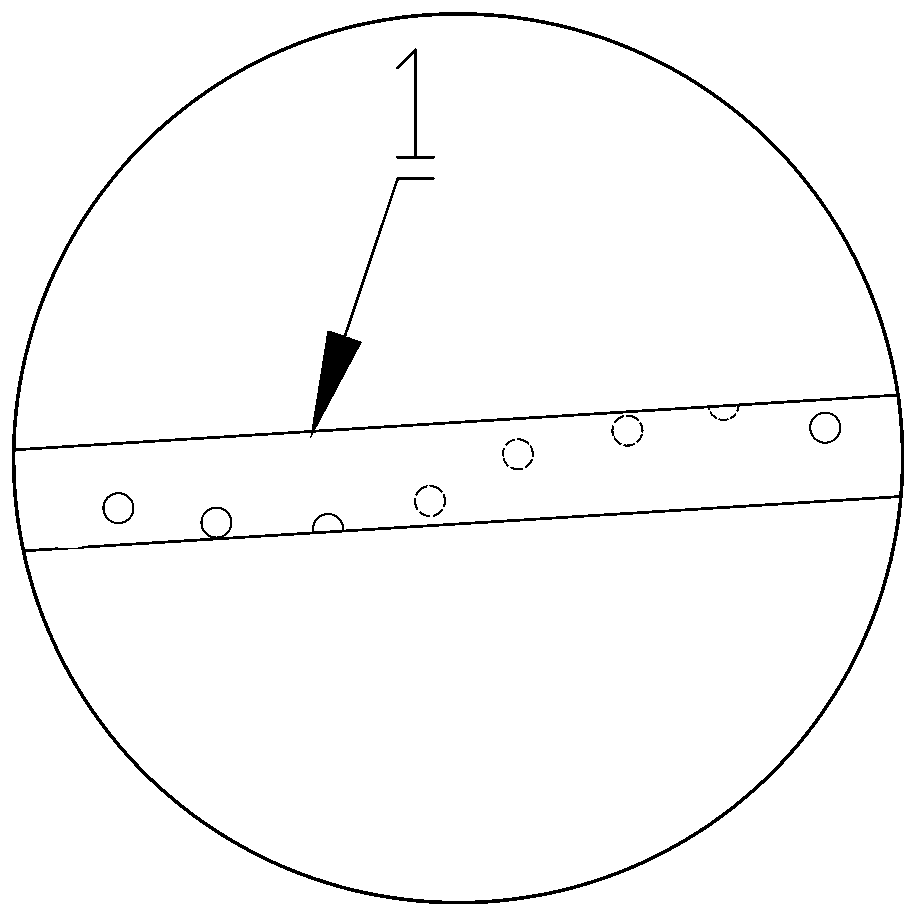
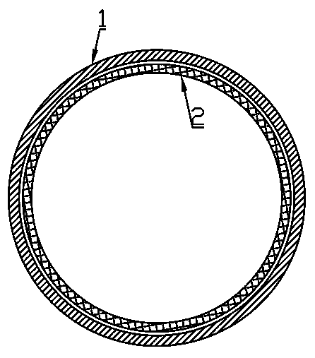
[0046] A porous pigtail catheter device such as Figure 1~4As shown, it includes a pigtail catheter 1, and one end in the shape of a curly pigtail is the head end 11 of the pigtail catheter 1, and the other end is the tail end 12; the pigtail catheter 1 is provided with a hollow inner core tube 2 that matches the pigtail catheter 1, as image 3 As shown; the inner core tube 2 stretches into the end opening in the pigtail conduit 1, and the other end of the inner core tube 2 is provided with a clip 21 that is clamped with the tail end 12; the inner core tube 2 is in the pigtail conduit 1 along the The pigtail catheter 1 moves in the length direction, and the contrast agent is passed into the inner core tube 2, and the contrast agent gushes out from the through hole 3 where the end of the inner core tube 2 extends into the pigtail catheter 1 for imaging; therefore, the pigtail catheter 1 After being implanted into the coronary a...

Embodiment 2

[0052] Example 2 Porous pigtail catheter device

[0053] A kind of porous pigtail catheter device, the distribution of through holes on the pigtail catheter is as follows Figure 5 As shown, the difference from Embodiment 1 is that the through holes 3 at both ends of the through hole group in this embodiment are located on the same axis. In addition, the distance between the first through hole 3 near the head end 11 and the head end 11 in the porous pigtail catheter device of the present invention is 20 cm or 10 cm or 5 cm, that is, 20 cm or 10 cm or 5 cm from the head end 11 of the pigtail catheter 1 Start opening the via group.

Embodiment 3

[0054] Example 3 Porous Pigtail Catheter Device

[0055] A porous pigtail catheter device such as Figure 6 As shown, the difference with Embodiment 1 is only that the number of through-hole groups offered on the pigtail conduit 1 is three, and the distance between two adjacent through-hole groups in the length direction of the pigtail conduit 1 is 15 cm, that is, the previous one The distance between the last through hole 3 of the through hole group and the first through hole 3 of the latter through hole group in the length direction of the pigtail conduit is 15 cm.


PUM


Abstract

The invention belongs to the technical field of medical products and in particular relates to a porous pig tail catheter device and application therein in blood vessel and cavity radiography. The porous pig tail catheter device comprises a pig tail catheter, wherein at least one through hole group is arranged on the pig tail catheter; the pig tail catheter is internally provided with a hollow inner core tube matched with the pig tail catheter; the inner core tube extend into an end opening inside the pig tail catheter; the inner core tube is moved inside the pig tail catheter along the lengthdirection of the pig tail catheter; a contrast agent is introduced into the inner core tube; and the contrast agent is gushed out from an end part of the inner core tube and flows out from through holes in the pig tail catheter to implement radiography. The device has the advantage that radiography can be implemented in different positions once being fixed for one time.

Description

technical field [0001] The invention belongs to the technical field of medical supplies, and in particular relates to a porous pigtail catheter device. Background technique [0002] Coronary angiography is a common and effective method for diagnosing coronary atherosclerotic heart disease (coronary heart disease). Coronary angiography is to extend a catheter such as a pigtail catheter through the femoral artery or other blood vessels to the root of the aorta of the heart for comparison. In this process, the aortic intima may be torn, and the blood flow enters the aortic wall through the tear to separate the media, and expands along the long axis of the aorta to form a true lumen and a false lumen. [0003] In endovascular treatment of aortic dissection with covered stent implantation, confirming that the catheter is in the true lumen is the key point for the success of the operation. At present, the identification of true lumen and false lumen mostly relies on experienced d...

Claims


Application Information

Patent Timeline
IPC IPC(8): A61M25/00
CPCA61M25/0043A61M25/008A61M2025/0057
Inventor 范卫东
Owner 范卫东
Why Eureka
Try Eureka