Material returning and feeding forming mechanism for special-shaped parts and method thereof
A technology of forming mechanism and material return mechanism, which is applied in the direction of metal processing equipment, feeding device, positioning device, etc., can solve the problems of low production efficiency of parts forming, waste of processing time, and poor processing dimensional accuracy, so as to improve processing efficiency, Guaranteed the effect of machining dimensional accuracy
- Summary
- Abstract
- Description
- Claims
- Application Information
AI Technical Summary
Problems solved by technology
Method used
Image
Examples
Embodiment 1
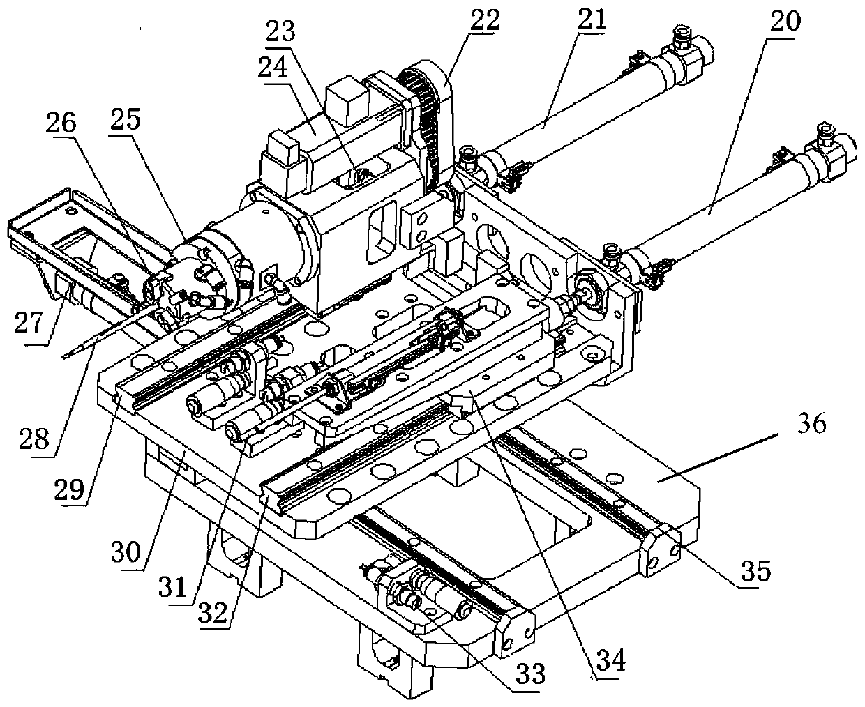
[0050] As shown in the figure, the return and feeding forming mechanism for special-shaped parts of the present invention includes a forming mechanism for rolling and extruding the blank workpiece 28 according to a preset angle, and a forming mechanism for orienting, returning and processing the blank workpiece 28. A dual-station orientation / returning mechanism with position conversion, the operating end of the dual-station orientation / removing mechanism is set correspondingly to the processing end of the forming mechanism, and is used to transfer the grasped blank workpiece 28 to the forming mechanism , and is used to exit the formed workpiece after processing and forming in the forming mechanism.
[0051] The double-station orientation / removal mechanism includes a station switch assembly, a station support plate 30 driven by the station switch assembly, and a tool set on the station support plate 30 for grabbing the blank workpiece 28 and rotating it to the pre-station. Set ...
Embodiment 2
[0064] On the basis of Embodiment 1, the method of the present invention based on the method for the return and feeding forming mechanism of special-shaped parts described in Embodiment 1 includes the following steps:
[0065] (1) The station of the double-station orientation / returning mechanism is switched to grab the workpiece assembly, grab the blank workpiece 28 through the grab assembly, and drive the grabbed blank workpiece 28 under the drive of the second synchronous motor 24 Rotate to a preset angle, and put the grabbed blank workpiece 28 into the second forming groove 18 of the linear mold 2 under the action of the driving cylinder 21;
[0066] (2) Start the clamping cylinder 13 of the locking assembly, so that the clamping cylinder 13 clamps the blank workpiece 28 in the linear mold 2;
[0067] (3) Start the first synchronous motor 6, under the action of the first synchronous belt 4, the linear mold 2 is moved along the guide rail, and the servo motor 7 of the circul...
Embodiment 3
[0071] On the basis of Embodiment 1, an inwardly recessed locking groove 19 is formed at the bottom of the linear mold 2 for the slider 3 to be locked in the locking groove 19 .
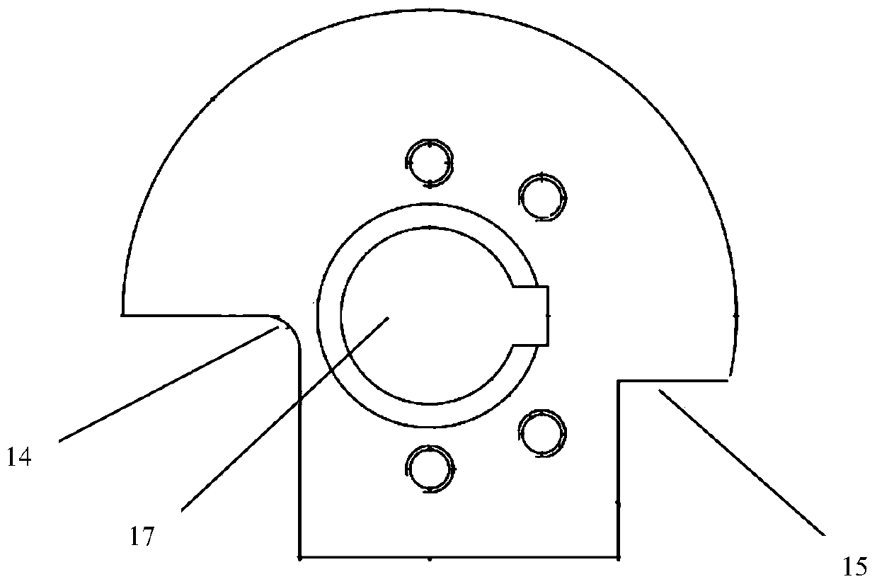
[0072] Furthermore, the first notch 14 and the second notch 15 formed by the circular mold 10 are used to facilitate the installation of the clamping cylinder 13, the connecting plate 11 and related parts, and are used as a reference during mold processing and installation. noodle.
[0073] Furthermore, two auxiliary cylinders are provided on the station support plate 30 , one auxiliary cylinder is set corresponding to the driving cylinder 21 , and the other auxiliary cylinder is set corresponding to the material return cylinder 20 .
[0074] Furthermore, a buffer cylinder 33 is provided on the station switching plate 36 , and the buffer cylinder 33 is arranged opposite to the station switching cylinder 27 .
PUM
 Abstract
Description
Claims
Application Information
 - R&D
- Intellectual Property
- Life Sciences
- Materials
- Tech Scout
- Unparalleled Data Quality
- Higher Quality Content
- 60% Fewer Hallucinations
Browse by: Latest US Patents, China's latest patents, Technical Efficacy Thesaurus, Application Domain, Technology Topic, Popular Technical Reports.
© 2025 PatSnap. All rights reserved.Legal|Privacy policy|Modern Slavery Act Transparency Statement|Sitemap|About US| Contact US: help@patsnap.com


