A method for machining microgrooves by shear-thickening abrasive flow compound grinding

A technology of abrasive flow and compound grinding, which is applied to machine tools suitable for grinding workpiece edges, grinding workpiece supports, grinding machine parts, etc. , Abrasive fluid is not easy to recover, etc., to improve the surface quality of the workpiece, simple installation and debugging, design, manufacture and installation are not complicated.

Active Publication Date: 2022-07-26
SOUTH CHINA UNIV OF TECH
View PDF10 Cites 0 Cited by
  • Summary
  • Abstract
  • Description
  • Claims
  • Application Information

AI Technical Summary

Problems solved by technology

[0007] 1. The construction of the abrasive spraying device is relatively complicated, and the abrasive fluid after spraying is not easy to recover, causing certain pollution to the environment
[0008] 2. The large parallel grinding wheel is used as the constraining wheel, which has high processing limitations. It is mainly suitable for finishing the outer circle, inner hole and large plane of the workpiece, and is not suitable for the processing of micro-groove structures.
[0009] 3. Relying on the rotation of the grinding wheel to drive the injected abrasive fluid to impact the surface of the workpiece to remove material. The abrasive fluid used has strong fluidity and weak holding force on the abrasive, resulting in low processing efficiency and processing quality.

Method used


Image

  • A method for machining microgrooves by shear-thickening abrasive flow compound grinding
  • A method for machining microgrooves by shear-thickening abrasive flow compound grinding
  • A method for machining microgrooves by shear-thickening abrasive flow compound grinding

Examples


Embodiment Construction

[0039] In the following description, the technical solutions are described in conjunction with the specific figures in order to fully understand the application of the present invention. However, the application of the present invention can be implemented in many other methods different from those described herein, and similar promotion examples made by those of ordinary skill in the art without creative work, all belong to the protection scope of the present invention.

[0040] The terms used in this specification are for the purpose of describing particular embodiments only and are not intended to limit the description. As used in the specification or embodiments and the appended claims, the singular forms "a," "the," and "the" are intended to include the plural forms as well, unless the context clearly dictates otherwise.

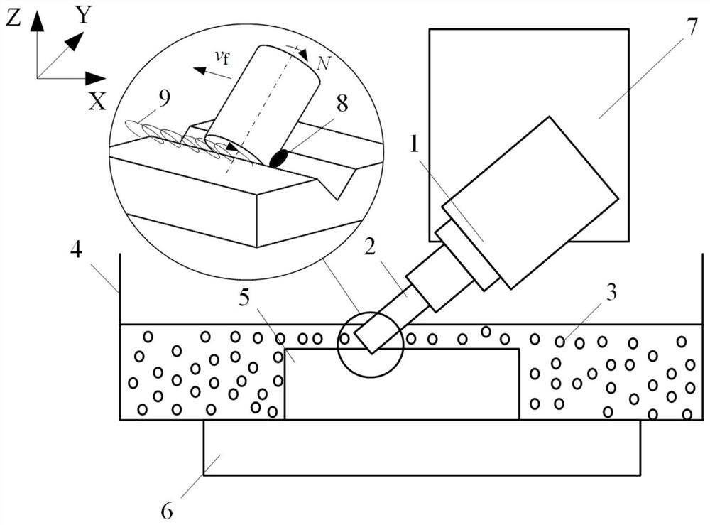
[0041]A new process for composite grinding of a material surface to process a functional surface of a V-groove structure, specifically, a method for com...


PUM

PropertyMeasurementUnit
diameteraaaaaaaaaa

Abstract

The invention discloses a method for composite grinding of microgrooves with shear-thickening abrasive streams, which comprises the following steps: adding abrasives to shear-thickening liquid and fully diffusing to form a thick suspension with shear-thickening effect; The thickened abrasive flow liquid is placed in the abrasive flow storage tank, the workpiece is clamped on the working platform, and the adjuster adjusts the inclination of the main shaft, so that the axis of the micro-grinding head forms a preset angle with the upper surface of the workpiece, and the workpiece and the micro-grinding head form a preset angle. At the same time, it is immersed in the shear-thickening abrasive flow liquid; the micro-grinding head is fed along the Y-axis and rotates at high speed in the shear-thickening abrasive flow liquid to form a flexible polishing head and produce a hydrodynamic pressure effect on the surface of the micro-groove; once After the machining is completed, the rotating work platform rotates the workpiece, the micro-grinding head is fed along the X-axis direction, and the end of the grinding head faces the other side of the micro-groove for abrasive flow compound grinding again, so as to obtain the same high-quality micro-groove surface on both sides. . The invention improves the surface quality of the workpiece while ensuring the machining dimensional accuracy, and is suitable for the machining of fine structures.

Description

technical field [0001] The invention belongs to the technical field of material surface machining, and in particular relates to a method for machining microgrooves by shearing and thickening abrasive flow compound grinding. Background technique [0002] In recent years, in order to obtain higher stability and reliability of product performance, the key components used in aviation, medical, optoelectronics and other fields have put forward higher and higher requirements on the machining accuracy, surface quality and surface integrity of the machining process. Require. [0003] Traditional grinding is a precision machining method that uses fixed abrasives to intermittently contact the workpiece surface at a high linear speed, thereby mechanically replicating the machined surface. However, micro-grinding tools are difficult to sharpen and dress, and wear quickly, resulting in poor surface quality and integrity. In order to solve the above problems, various auxiliary grinding ...

Claims


Application Information

Patent Timeline
Patent Type & Authority Patents(China)
IPC IPC(8): B24B1/00B24B31/116B24B31/12B24B31/14B24B41/04B24B41/06
CPCB24B1/00B24B31/116B24B31/12B24B31/14B24B41/04B24B41/06
Inventor 谢晋罗宜毫陈钊杰何铨鹏
Owner SOUTH CHINA UNIV OF TECH
Why Eureka
Try Eureka