
Cutting device for machining building materials

A technology for cutting devices and building materials, applied in shearing devices, pipe shearing devices, metal processing equipment, etc., can solve problems affecting normal use, pipe angle errors, etc., to achieve beautiful incisions, high precision, and improve the effect of cutting quality.

Inactive Publication Date: 2020-05-15
赣州全冠建材有限公司
View PDF11 Cites 4 Cited by
  • Summary
  • Abstract
  • Description
  • Claims
  • Application Information

AI Technical Summary

Problems solved by technology

[0003] In the process of building materials processing, it is often necessary to cut the pipe into small sections with different angles for subsequent splicing. The existing pipe cutting device basically uses manual hand-held pipes when cutting the pipes at different angles, so that the pipe and the cutting piece Form a rough angle, so that there is a large error in the angle of the cut pipe, which will affect the subsequent normal use

Method used


Image

  • Cutting device for machining building materials
  • Cutting device for machining building materials
  • Cutting device for machining building materials

Examples


Embodiment 1

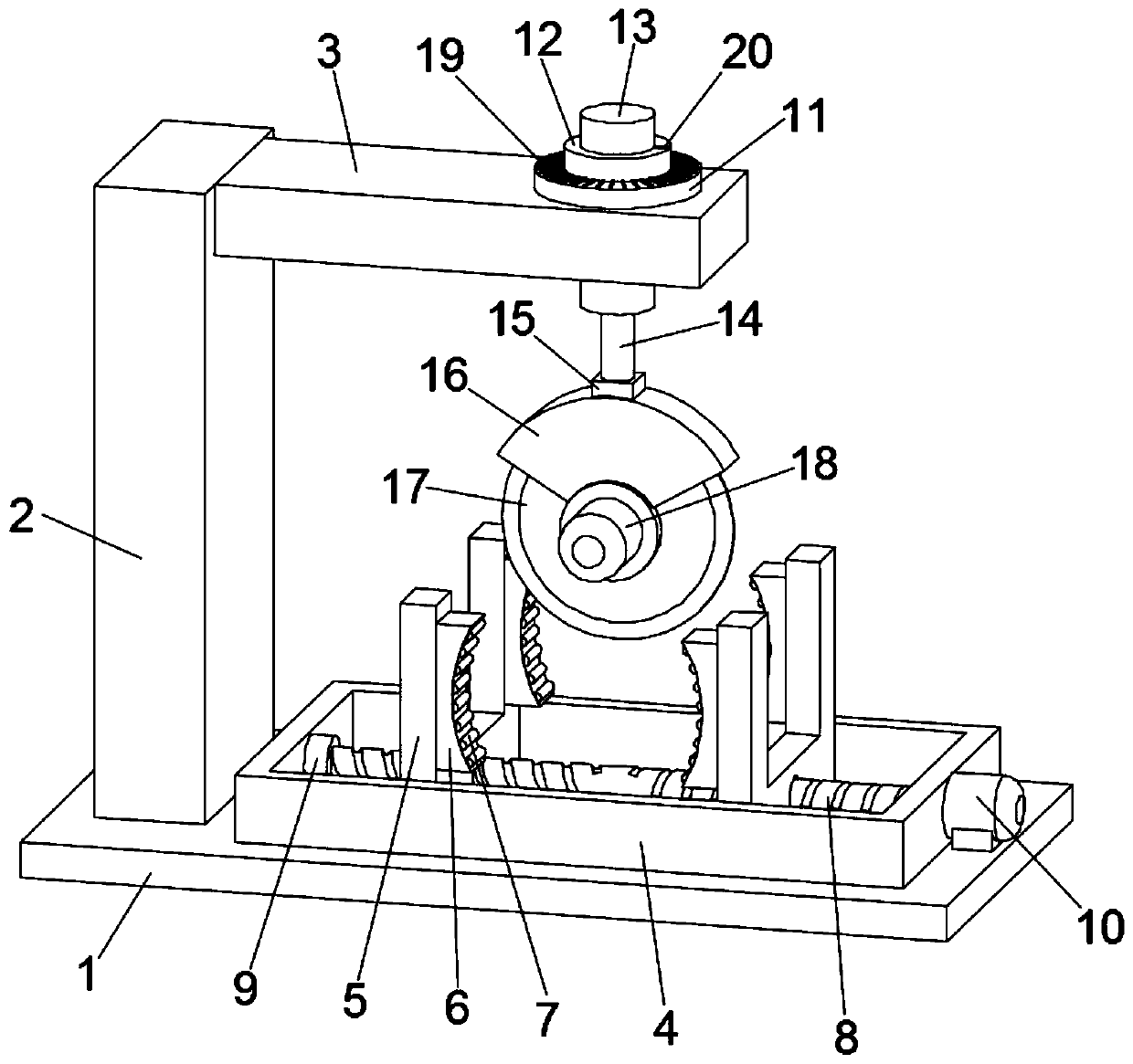
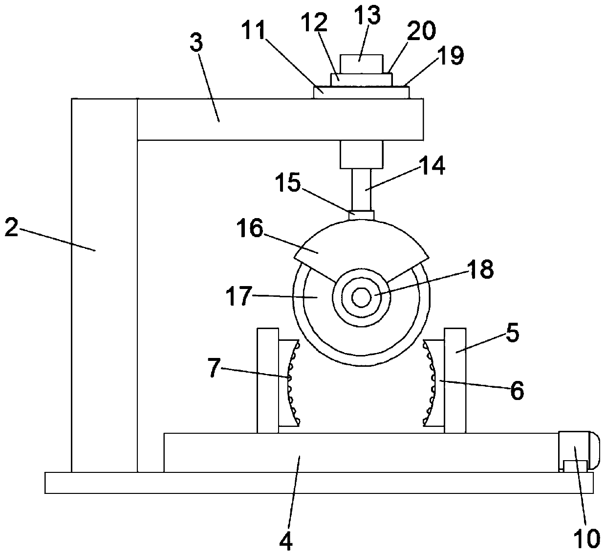
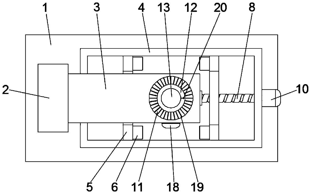
[0024] see figure 1 , a cutting device for building materials processing, comprising a base plate 1 and a support plate 2, the support plate 2 is vertically installed on one side of the base plate 1, a top plate 3 is fixed on the top of the support plate 2, and a chute is also fixed on the base plate 1 4. Two sliders 5 are embedded symmetrically in the chute 4, and a block 6 for fixing the pipe is installed on the side wall of the slider 5, and a screw 8 is installed horizontally in the chute 4, so that The two ends of the screw rod 8 are provided with threads with opposite directions of rotation, and the two sliders 5 are respectively helically sleeved on the threads at both ends of the screw rod 8. One end of the screw rod 8 is rotated with a bearing seat 9, and the other end is connected with a mobile motor 10; A fixed disk 11 is installed on the upper end surface of the top plate 3, and a damping drum 12 is provided in the rotation sleeve of the fixed disk 11, and a dial 1...

Embodiment 2

[0034] A cutting device for building material processing, comprising a base plate 1 and a support plate 2, the support plate 2 is vertically installed on one side of the base plate 1, a top plate 3 is fixed on the top of the support plate 2, and a chute 4 is also fixed on the base plate 1 , two sliders 5 are installed symmetrically in the chute 4, blocks 6 for fixing pipes are installed on both sides of the slider 5, a screw 8 is horizontally installed in the chute 4, and the two sides of the screw 8 are The ends are provided with threads with opposite directions of rotation, and the two sliders 5 are respectively helically sleeved on the threads at both ends of the screw rod 8. One end of the screw rod 8 is rotated with a bearing seat 9, and the other end is connected with a mobile motor 10; A fixed disk 11 is installed on the end surface, and a damping drum 12 is set in the rotation sleeve of the fixed disk 11. A dial 19 is arranged on the upper end surface of the fixed disk ...


PUM


Abstract

The invention discloses a cutting device for machining building materials. The cutting device comprises a base plate and a support plate; a chute is fixed on the base plate; two slide blocks are symmetrically mounted in the chute; clamping blocks for fixing pipes are mounted on the side walls of the slide blocks; a moving mechanism is mounted in the chute; a fixed disc is mounted on the upper endsurface of a top plate; a damping rotary drum is rotationally sleeved in the fixed disc; a dial is peripherally arranged on the upper end surface of the fixed disc; a pointer for indicating scales isarranged on the damping rotary drum; and a cutting device is mounted in the damping rotary drum. The cutting device for machining the building materials is provided with the damping rotary drum capable of being rotatably adjusted above a cutting blade, realizes precise adjustment of the cutting angle of the cutting blade through fit use of the pointer and the dial, and is convenient and fast in operation, high in precision and stable and reliable in cutting angle.

Description

technical field [0001] The invention relates to the technical field of building material processing, in particular to a cutting device for building material processing. Background technique [0002] Building materials are a general term for materials used in civil engineering and construction engineering. They can be divided into structural materials, decorative materials and some special materials. Structural materials include wood, bamboo, stone, cement, concrete, metal, bricks, ceramics, glass, Engineering plastics, composite materials, decorative materials include various coatings, paints, coatings, veneers, various colored tiles, glass with special effects, etc. Special materials refer to waterproof, moisture-proof, anti-corrosion, fire-proof, flame-retardant, sound insulation, heat insulation , insulation, sealing, etc. [0003] In the process of building materials processing, it is often necessary to cut the pipe into small sections with different angles for subseque...

Claims


Application Information

Patent Timeline
Patent Type & Authority Applications(China)
IPC IPC(8): B23D21/00B23D33/02B23D33/00
CPCB23D21/00B23D33/00B23D33/02
Inventor 肖立霞
Owner 赣州全冠建材有限公司
Learn More