Laser welding assembly of special-shaped cylinder component, laser welding machine and welding method

A laser welding machine and laser welding technology, used in laser welding equipment, welding equipment, applications, etc., can solve the problems of welding leakage, scrapped cylinder, poor welding seam forming consistency, etc., and achieve improved consistency and ensure stability. , the effect of improving consistency

Active Publication Date: 2020-05-15
AVIC BEIJING AERONAUTICAL MFG TECH RES INST
View PDF8 Cites 1 Cited by
  • Summary
  • Abstract
  • Description
  • Claims
  • Application Information

AI Technical Summary

Problems solved by technology

In the entire manufacturing process, the overall splicing technology between special-shaped cylinders is the most difficult. During the welding process, the gravitational force of the molten pool is not perpendicular to the surface of the cylinder components, which causes the flow direction of the molten pool to change, so that the weld shape after welding is consistent. Poor performance, inconsistent weld surface width
[0003] When the circular splicing of the cylinders between the special-shaped cylinders involves all-position welding such as flat welding, oblique welding, vertical welding and overhead welding in the welding process, due to oblique welding, vertical welding, overhead welding and other welding At the posture, the gravitational force of the molten pool is not perpendicular to the plate, resulting in a change in the flow direction of the molten pool, poor weld formation consistency, and inconsistent weld surface width
When laser welding encounters a circumferential weld in a large special-shaped cylindrical member, it is often found that the weld width is inconsistent during laser welding. What's more, if the entire weld seam collapses and breaks down, it will eventually lead to the scrapping of the entire cylinder

Method used


Image

  • Laser welding assembly of special-shaped cylinder component, laser welding machine and welding method
  • Laser welding assembly of special-shaped cylinder component, laser welding machine and welding method
  • Laser welding assembly of special-shaped cylinder component, laser welding machine and welding method

Examples


Embodiment Construction

[0033] Embodiments of the present invention will be further described in detail below in conjunction with the accompanying drawings and examples. The detailed description and accompanying drawings of the following embodiments are used to illustrate the principles of the present invention, but cannot be used to limit the scope of the present invention, that is, the present invention is not limited to the described embodiments, without departing from the spirit of the present invention Any modification, substitution and improvement of parts, components and connection methods are covered under.

[0034] It should be noted that, in the case of no conflict, the embodiments in the present application and the features in the embodiments can be combined with each other.

[0035] The following will refer to the attached figure 1 - attached Figure 5 The present application will be described in detail in conjunction with the embodiments.

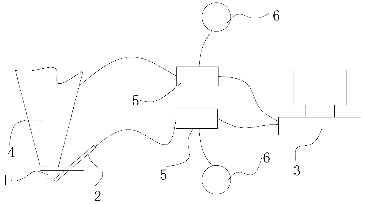
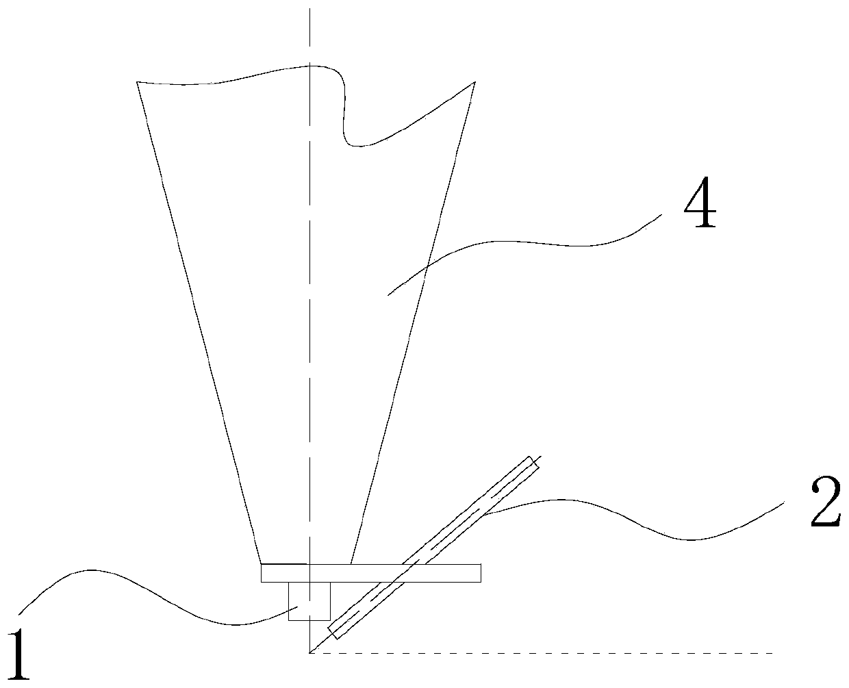
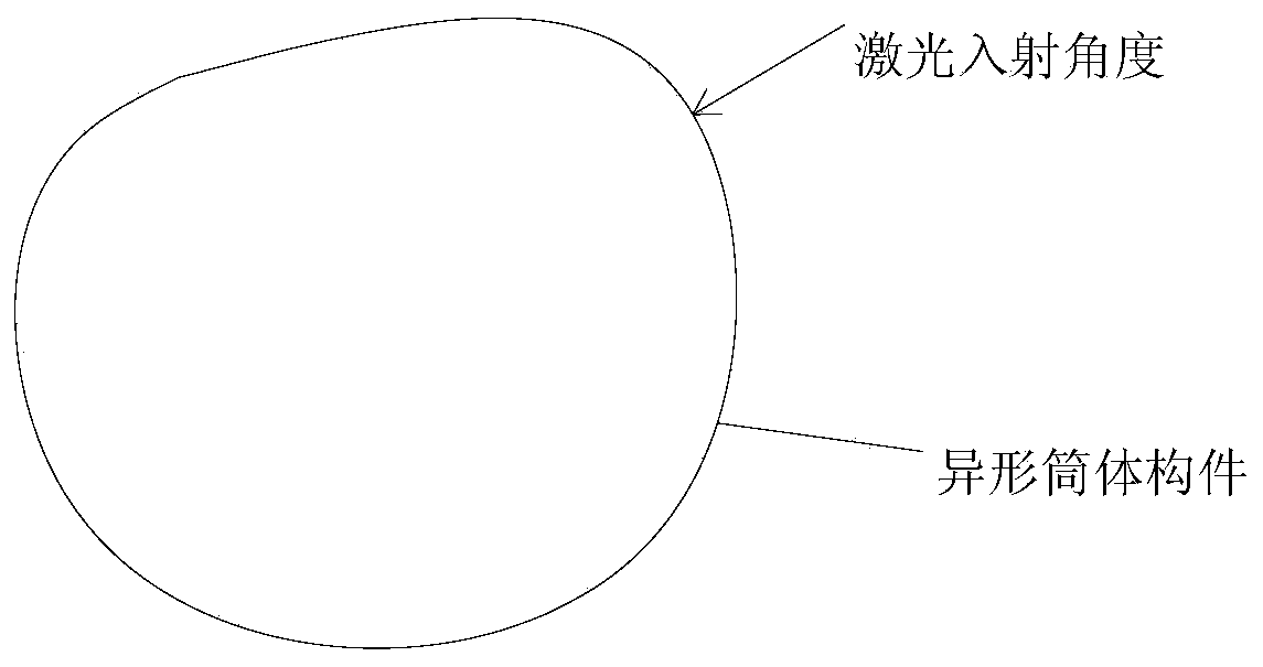
[0036] See attached figure 1 And attached ...


PUM


Abstract

The invention relates to a laser welding assembly of a special-shaped cylinder component, a laser welding machine and a welding method. The laser welding assembly comprises a coaxial gas nozzle, a side gas nozzle and a control module; the coaxial gas nozzle is arranged on a welding head of the laser welding machine, is coaxial with the welding head, and is used for spraying shielding gas with certain force to a to-be-welded part on the special-shaped cylinder component; the side gas nozzle is arranged on one side of the welding head and is used for spraying the shielding gas with certain forceto the to-be-welded part; and the control module is connected with the control ends of the coaxial gas nozzle and the side gas nozzle, and is used for adjusting the strength of the coaxial gas nozzleand the side gas nozzle for spraying the shielding gas according to a preset motion path as well as gravity and surface tension of molten pools at different welding positions. According to the laserwelding assembly of the special-shaped cylinder component, the laser welding machine and the welding method, the stability of molten pool structures is ensured, forming consistency of obtained weld joints is greatly improved, the perforation phenomenon is not likely to occur, and finally high-quality weld joint forming is obtained.

Description

technical field [0001] The invention relates to the technical field of laser welding, in particular to a laser welding assembly of a special-shaped cylinder member, a laser welding machine and a welding method. Background technique [0002] Special-shaped thin-walled cylinder components are often found in aviation and aerospace structural parts, such as aviation air inlets, exhaust ducts and other structural parts. The main features of this type of structure are large structure, thin cylinder, and limited by aerodynamic requirements, its shape is mostly a complex three-dimensional curved surface configuration, and its geometric shape is asymmetrical. At present, the manufacturing process of large thin-walled cylindrical components is generally carried out in the manner of split forming, welding the cylinder, and splicing the whole cylinder. For example, the cylinder member is divided into multiple petals, and the single petals are spliced ​​into a cylinder member by laser w...

Claims


Application Information

Patent Timeline
Patent Type & Authority Applications(China)
IPC IPC(8): B23K26/28B23K26/14B23K26/70
CPCB23K26/14B23K26/28B23K26/702B23K2101/04
Inventor 王彬曾元松杨璟马旭颐
Owner AVIC BEIJING AERONAUTICAL MFG TECH RES INST
Why Eureka
Try Eureka