Robotic arm control method based on man-machine fusion

A control method and technology of manipulators, applied in manipulators, program-controlled manipulators, manufacturing tools, etc., can solve problems such as direct control, difficulty in completely obtaining on-site 3D information, discrimination errors, etc., and achieve good heterogeneous control effects

Active Publication Date: 2020-05-15
ZHEJIANG UNIV
View PDF8 Cites 3 Cited by
  • Summary
  • Abstract
  • Description
  • Claims
  • Application Information

AI Technical Summary

Problems solved by technology

[0004] Based on the aforementioned remote control method, the safety impact on the operator can be well avoided. However, it is difficult to completely obtain all on-site 3D information due to the fact that people judge the on-site environment and distance through the impact data. Directly control the robot's mechanical arm movement based on the acquired joint data of the human arm during the demonstration movement
[0005] In addition, in the process of operation, there are the following problems. Although the mechanical arm has a humanoid structure, it is still difficult to have an isomorphic structure with the human arm, such as different degrees of freedom or arm lengths, that is, they are usually heterogeneous, making it difficult to use human arms. The joint data of the arm directly controls the operation of the humanoid manipulator. Although the theoretical data of the manipulator control can be directly obtained by using the workspace matrix, due to the heterogeneity of the two, the theoretical data calculated directly cannot be directly executed in some cases. , resulting in the following control cannot be realized in some cases

Method used


Image

  • Robotic arm control method based on man-machine fusion
  • Robotic arm control method based on man-machine fusion
  • Robotic arm control method based on man-machine fusion

Examples


Embodiment

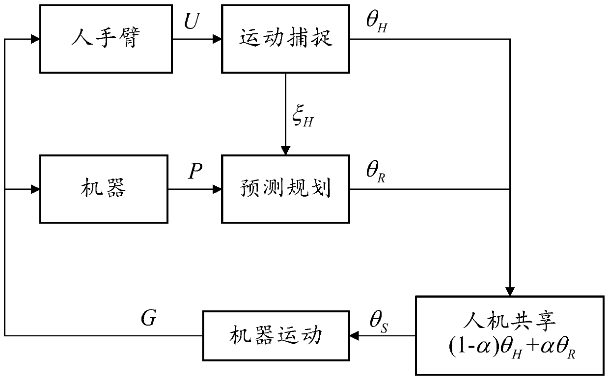
[0056] Such as figure 1 As shown, the man-machine fusion-based robotic arm control method of the present invention includes an acquisition step S1, a mapping step S2, a planning step S2, a fusion step S4 and a control step S5, and the specific process is as follows:

[0057] Obtaining step S1, acquiring the surrounding real-time scene images of the target object.

[0058] Specifically, the camera mounted on the robot or the camera arranged at the work site is used to obtain the scene image of the robot during the work process. The number of cameras is arranged according to the actual situation, and the depth information of the work scene can also be obtained based on the deployment of the depth camera.

[0059] In the mapping step S2, the real-time scene image is displayed on the operating end, and the series data of the human arm joint angle during the demonstration movement of the human arm are obtained, and the human arm joint angle data is mapped into the mapped joint angl...


PUM


Abstract

The invention relates to a robotic arm control method based on man-machine fusion, and belongs to the technical field of robot control. The control method comprises the following steps that (1) a peripheral real-time scene image of a target object is obtained; (2) the real-time scene image is displayed at an operation end, a human arm joint angle data is obtained, and the human arm joint angle data is mapped to a mapped joint angle data theta H for controlling the robotic arm; (3) the position data of the target object is predicted according to the current position, a preset operation path isplanned according to a polynomial path planning method, and a planned joint angle data theta R for controlling the robotic arm is obtained; and (4) the current execution joint angle data of the robotic arm is calculated according to the formula theta S equal to (1-alpha) theta H + alpha theta R; and the weight alpha is increased along with increase of confidence degree of the target object predicted by the robotic arm. The method can well set the advantages and disadvantages of the motion of the human arm and the robotic arm, and the robotic arm control method is easier to remotely control theaction of the robotic arm.

Description

technical field [0001] The invention relates to the technical field of robot control, in particular to a control method of a heterogeneous mechanical arm based on human-machine fusion. Background technique [0002] With the development of robot technology, in order to ensure the personal safety of operators, cameras are usually mounted on robots, such as the panoramic imaging system disclosed in the patent literature with the publication number CN108082415A, or a camera is arranged at its work site to obtain the scene To avoid the need for operators to enter the deep sea operation environment, bomb disposal and mine clearance and other operating environments that will affect the safety of operators. [0003] And after obtaining the environment scene image, the on-site operation action is simulated by the human arm, and by obtaining the joint angle data of the human arm during the on-site operation action, for example, the acquisition target walking method disclosed in the pa...

Claims


Application Information

Patent Timeline
Patent Type & Authority Applications(China)
IPC IPC(8): B25J9/16B25J3/00
CPCB25J3/00B25J9/1664B25J9/1697
Inventor 杨灿军朱元超魏谦笑武鑫王楚璇
Owner ZHEJIANG UNIV
Why Eureka
Try Eureka