Joint rotating angle auxiliary measuring system and method of serial rotary joint mechanical arm

A joint angle and auxiliary measurement technology, applied in the direction of manipulators, manufacturing tools, joints, etc., to achieve the effect of simplifying the equipment installation process, simplifying the joint angle measurement process, and low implementation cost

Inactive Publication Date: 2020-05-15
SHANDONG UNIV
View PDF3 Cites 4 Cited by
  • Summary
  • Abstract
  • Description
  • Claims
  • Application Information

AI Technical Summary

Problems solved by technology

[0005] Aiming at the problem of auxiliary measurement of the joint angle of the series rotary joint manipulator, the present invention proposes an auxiliary joint angle measurement method of the series rotary joint manipulator, by including an industrial-grade three-axis gyroscope, an industrial-grade three-axis accelerometer and The attitude detection unit of the industrial-grade three-axis magnetometer is fixed on each joint of the tandem rotary joint manipulator with any attitude, and the quaternion information output by each attitude measurement unit during the movement of the manipulator is used to solve the real-time calculation of each joint of the manipulator. Rotation angle, the purpose of this measurement method is to provide an easy-to-deploy, low-cost, high-flexibility auxiliary measurement method for joint rotation angles for tandem rotary joint manipulators

Method used


Image

  • Joint rotating angle auxiliary measuring system and method of serial rotary joint mechanical arm
  • Joint rotating angle auxiliary measuring system and method of serial rotary joint mechanical arm
  • Joint rotating angle auxiliary measuring system and method of serial rotary joint mechanical arm

Examples


Embodiment 1

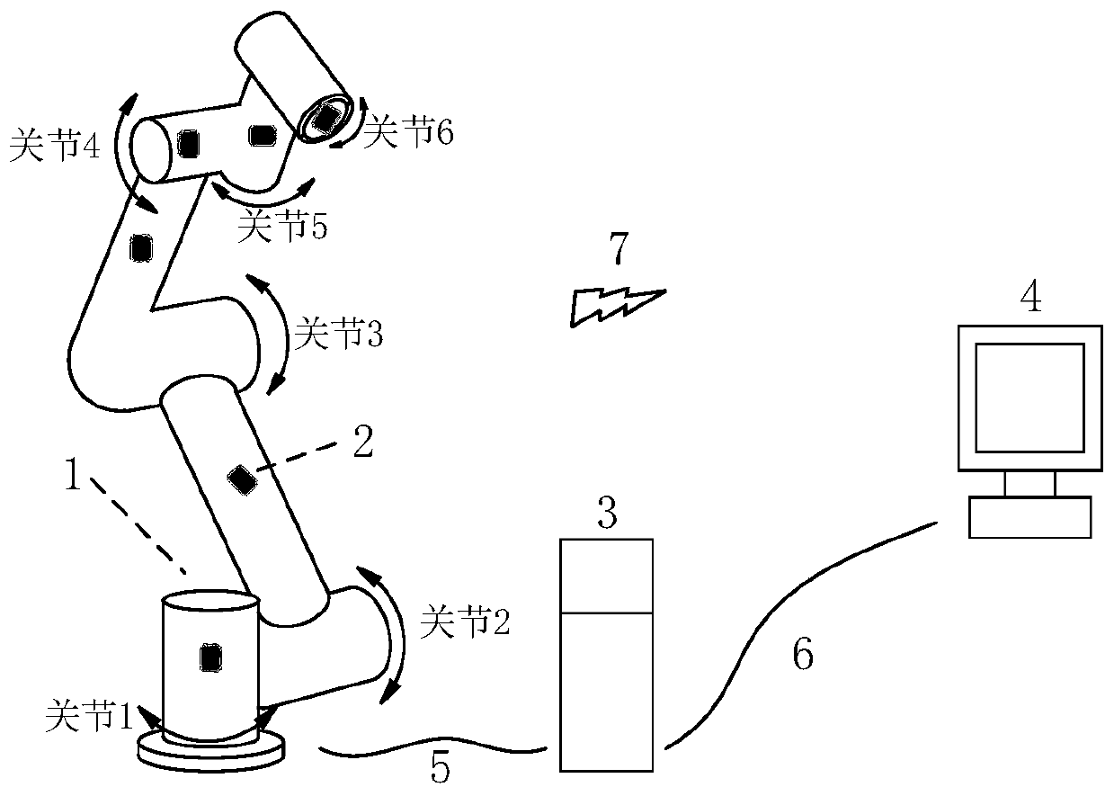
[0054] figure 1 It is a structural schematic diagram of a series rotary joint manipulator joint angle auxiliary measurement system constructed according to a preferred embodiment of the present invention, wherein 1 is a series rotary joint manipulator, 2 is an attitude measurement unit, 3 is a control cabinet of the manipulator, 4 is the computer, 5 is the cable between the robot arm 1 and the control cabinet 3, 6 is the network cable connecting the control cabinet 3 to the computer 4, and 7 is the communication between each attitude measurement unit 2 fixed on the robot arm 1 and the computer 4 Way.

[0055] The mechanical arm 1 can be any multi-degree-of-freedom series rotary joint mechanical arm in practice. For convenience, figure 1 What is shown in is a common six-degree-of-freedom series rotary joint manipulator.

[0056] The number of the attitude measurement units 2 should match the degrees of freedom of the robot arm, and the attitude measurement units 2 can be fixe...


PUM


Abstract

The invention provides a joint rotating angle auxiliary measuring system of a serial rotary joint mechanical arm. The joint rotating angle auxiliary measuring system comprises an attitude measuring unit and a computer. The attitude measuring unit comprises a microprocessor, a three-axis accelerometer, a three-axis gyroscope and a three-axis magnetometer, wherein the three-axis accelerometer, the three-axis gyroscope and the three-axis magnetometer are connected with the microprocessor through electric signals. The attitude measuring unit is further provided with a fixed end, and the attitude measuring unit is fixedly arranged at any position of any plane of each joint of the mechanical arm through the fixed end. The attitude measuring unit is in communication connection with the computer.The computer is used for calculating the joint rotating angles of the mechanical arm according to attitude information of the attitude measuring unit. Flexible, convenient, efficient and accurate joint rotating angle measuring is achieved without being affected by the environment. Measuring is not limited by the environment, joint rotating angle information of the serial mechanical arm in the movement process can be obtained through calculation, and the measuring process of the joint rotating angles of the mechanical arm is greatly simplified.

Description

technical field [0001] The invention belongs to the technical field of measuring the joint rotation angle of a mechanical arm, and relates to an attitude detection unit including an industrial-grade three-axis gyroscope, an industrial-grade three-axis accelerometer, and an industrial-grade three-axis magnetometer to measure the joints of a series rotating joint mechanical arm. The measurement method of the auxiliary measurement of the rotation angle. Background technique [0002] The high-precision encoder system contained in the robotic arm is the main means for the user to obtain the angle information of each joint of the robotic arm during motion. Usually, in order to more accurately monitor the position and attitude of the robotic arm during motion, users usually introduce an auxiliary joint angle measurement system. [0003] This joint angle auxiliary measurement system can be used as an auxiliary means to monitor the joint angle information of the manipulator, and pro...

Claims


Application Information

Patent Timeline
Patent Type & Authority Applications(China)
IPC IPC(8): B25J17/00B25J19/00
CPCB25J17/00B25J19/0095
Inventor 田新诚徐小龙周乐来马昕宋锐
Owner SHANDONG UNIV
Why Eureka
Try Eureka