
Automatic argon-blowing butt-joint device

A docking device and automatic technology, applied in casting melt containers, manufacturing tools, metal processing equipment, etc., can solve problems such as air leakage and molten steel backflow, and achieve the effect of improving sealing, reducing labor intensity and facilitating docking.

Inactive Publication Date: 2020-05-15
江苏博壹重工有限公司
View PDF4 Cites 3 Cited by
  • Summary
  • Abstract
  • Description
  • Claims
  • Application Information

AI Technical Summary

Problems solved by technology

However, accurate positioning and alignment are required during the connection between the male and female connectors, otherwise air leakage is likely to occur, and molten steel in the ladle may be poured backward

Method used


Image

  • Automatic argon-blowing butt-joint device
  • Automatic argon-blowing butt-joint device

Examples


Embodiment 1

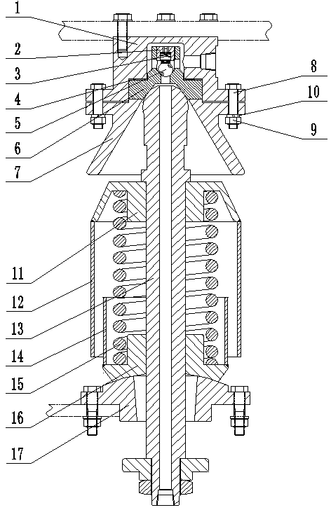
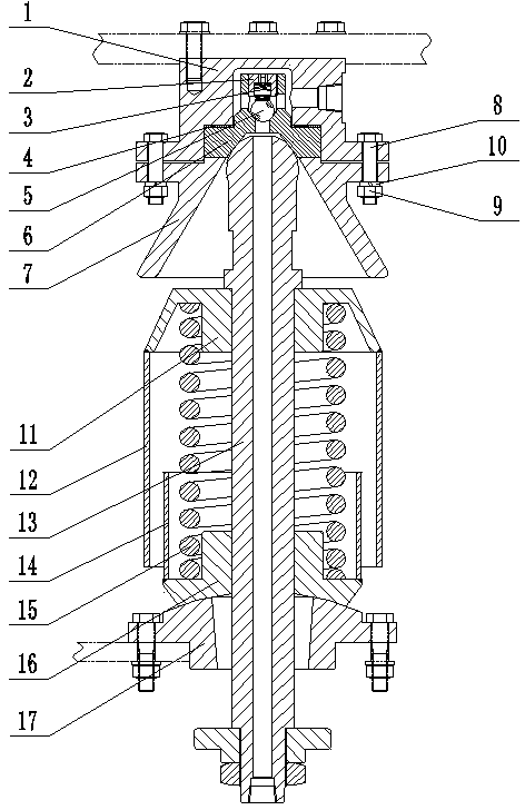
[0014] Embodiment 1, as shown in the figure: an automatic argon blowing docking device, including a male head and a female head, the male head and the female head are snapped together, the female head is fixed on the outer wall of the ladle, and the The male head is fixed on the base 17, the female head includes a joint 1, the joint 1 is provided with a cavity, and the cavity in the joint 1 is connected to the through port provided on the side wall of the joint 1 In general, the outer wall of the joint 1 at the top of the cavity is provided with an adjusting screw plug 2, and the adjusting screw plug 2 passes through the joint 1 and is closely combined with the adjusting spring 3 in the cavity, and the adjustment spring 3 is provided below There is a steel ball 5, a copper sleeve 6 is provided under the steel ball 5, and an air hole is provided in the middle of the copper sleeve 6, and the copper sleeve 6 is embedded in the joint 1, and the copper sleeve 6 and the A gasket 4 i...

Embodiment 2

[0015] Embodiment 2, an automatic argon blowing docking device, a spring washer 10 is provided between the fixing nut 9 and the conical flange 7 . The air holes, cavities and passage ports are in communication. The lower part of the copper sleeve 6 is provided with a hemispherical groove, and the hemispherical groove is closely combined with the top of the argon gas tube 13, and the top of the argon gas tube 13 is a spherical end. The sealing gasket 4 is an asbestos rubber plate. Through the cooperation between the spherical end on the top of the argon tube 13 and the hemispherical groove on the lower part of the copper sleeve 6, good sealing performance is achieved, and the position error compensation range caused by inclination is large, and it is easy to connect.


PUM


Abstract

The invention discloses an automatic argon-blowing butt-joint device. The automatic argon-blowing butt-joint device comprises a male head and a female head, wherein the male head is in blocking connection to the female head; the female head is fixed on the outer wall of a steel ladle; the male head is fixed on a base; the female head comprises a joint, and a cavity is arranged in the joint; the cavity in the joint communicates with a pass-through hole in the side wall of the joint; a regulating screw plug is arranged on the outer wall of the joint at the top end of the cavity; the regulating screw plug passes through the joint and is tightly combined with a regulating spring in the cavity; a steel ball is arranged below the regulating spring; a copper sleeve is arranged below the steel ball; a gas hole is formed in the middle of the copper sleeve; the copper sleeve is embedded into the joint; a sealing cushion is arranged between the copper sleeve and the joint; the lower portion of the joint is connected to a conical flange; and the joint and the conical flange are connected through a fixed bolt and a fixed nut. The conical flange is arranged, so that an argon-gas tube can slide to the copper sleeve after being in contact with the inner wall of the conical flange while the argon-gas tube is in butt joint to the copper sleeve, and therefore, fuzzy butt-joint can be realized, butt-joint precision is high, labor intensity of a worker is relieved, and the argon-gas tube is conveniently butt-jointed by the worker.

Description

technical field [0001] The invention relates to the technical field of external refining of molten steel, in particular to an automatic argon blowing butt joint device. Background technique [0002] Ladle argon blowing treatment, also known as steel liquid argon blowing treatment, is a simple out-of-furnace refining method for degassing molten steel and removing non-metallic inclusions. This method has simple process, cheap equipment and remarkable refining effect. At present, in the known argon blowing device at the bottom of the ladle, it is generally arranged on the side of the ladle, adopts upper and lower male and female connectors, and uses springs as buffer and position compensation. In the process of connecting the male and female connectors, accurate positioning and alignment are required, otherwise air leakage is prone to occur, and molten steel in the ladle may be poured backward. Contents of the invention [0003] The object of the present invention is to add...

Claims


Application Information

Patent Timeline
Patent Type & Authority Applications(China)
IPC IPC(8): C21C7/072B22D41/58
CPCB22D41/58C21C7/072
Inventor 于露殷大方戴引江周兆俊
Owner 江苏博壹重工有限公司
Learn More