Multi-frequency resistivity measuring device

A measuring device and resistivity technology, applied in electrical/magnetic detection for well logging records, wellbore/well components, earthwork drilling and production, etc., to achieve excellent efficiency, energy saving and consumption reduction, simple and efficient operation

Active Publication Date: 2020-05-15
UNIV OF ELECTRONIC SCI & TECH OF CHINA
View PDF6 Cites 6 Cited by
  • Summary
  • Abstract
  • Description
  • Claims
  • Application Information

AI Technical Summary

Problems solved by technology

[0004] The purpose of the present invention is to solve the problems existing in the traditional multi-frequency time-division logging instrument, and propose a multi-frequency resistivity measurement device, which can improve the measurement efficiency and timeliness of the instrument through multi-frequency simultaneous measurement, and can also Reduce system power consumption to a certain extent

Method used


Image

  • Multi-frequency resistivity measuring device
  • Multi-frequency resistivity measuring device
  • Multi-frequency resistivity measuring device

Examples


Embodiment 1

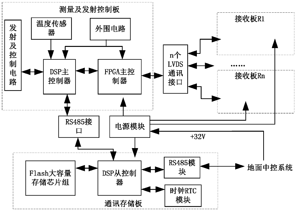
[0028] Embodiments of the present invention provide a multi-frequency resistivity measuring device, such as figure 1As shown, it includes a measurement and emission control board, a power module, a communication storage board and n receiving boards. The measurement and emission control board is respectively connected to n receiving boards through n LVDS communication interfaces. The RS485 interface is connected to the communication storage board, the input terminal of the power module is connected to the ground central control system, and its output terminal is respectively connected to the measurement and emission control board, the communication storage board and each receiving board, and the communication storage board is also connected to the ground central control system connect.

[0029] The measurement and emission control board includes FPGA main controller, DSP main controller, emission and control circuit, temperature sensor and peripheral circuit.

[0030] The DSP ...

Embodiment 2

[0065] A multi-frequency resistivity measurement method such as Figure 5 As shown, the following steps S1-S13 are included:

[0066] S1. Power on the multi-frequency resistivity measuring device, and perform initialization and self-test.

[0067] S2. Put the multi-frequency resistivity measuring device on standby, and wait for receiving instructions.

[0068] S3. Judging whether the received instruction is an instruction to start measurement, if so, proceed to step S4, otherwise perform related operations according to the instruction requirements, and return to step S2.

[0069] In the embodiment of the present invention, related operations include instrument status query, memory data reading, Flash formatting and parameter configuration.

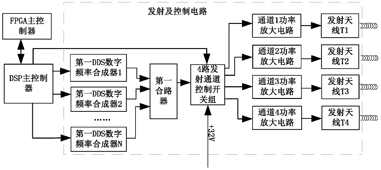
[0070] S4. Enable multiple first DDS digital frequency synthesizers to generate different frequency transmitting signals through the DSP main controller on the measuring and transmitting control board, and integrate multiple transmitting...


PUM


Abstract

The invention discloses a multi-frequency resistivity measuring device, and relates to the technical field of resistivity logging. Multiple frequencies can be simultaneously measured under the condition of ensuring sufficient measurement precision of signals. According to the multi-frequency resistivity measuring device, a multi-frequency mixed waveform is subjected to sampling fitting treatment,digital DPSP operation is combined to separate waveforms of the various frequency signals, the single frequency signal is subjected to quadrature separation treatment, the phase difference and the amplitude ratio of each frequency signal are obtained, and finally resistivity information detected at different frequencies of a stratum is obtained. According to the multi-frequency resistivity measuring device, the measurement efficiency and the measurement timeliness of the device are improved in a mode of multi-frequency simultaneous measurement, and meanwhile, the power consumption of the system can be reduced to a certain extent.

Description

technical field [0001] The invention belongs to the technical field of resistivity logging, and in particular relates to the design of a multi-frequency resistivity measuring device. Background technique [0002] At present, with the rapid development of resistivity logging technology, most of the instrument systems in the field of logging are single-frequency and time-sharing measurements, and different frequencies are switched to realize formation detection. For example, the LWD tool uses three frequencies for measurement, namely 2MHz, 400KHz, and 100KHz. During the detection process, different frequencies are alternately switched to achieve multi-frequency measurement. The logging tool itself has multiple transmitting antennas and receiving antennas, and only one transmitting antenna is allowed to be in the transmitting state at any time, and the transmitting coils transmit alternately. If there are multiple transmitting frequencies, while using multi-frequency time-divi...

Claims


Application Information

Patent Timeline
IPC IPC(8): E21B49/00G01V3/18
CPCE21B49/00G01V3/18
Inventor 管国云聂在平孙向阳
Owner UNIV OF ELECTRONIC SCI & TECH OF CHINA
Why Eureka
Try Eureka