
Auxiliary equipment for maintenance of hydraulic rod in hydraulic single column press

A technology of auxiliary equipment and hydraulic press, which is applied in the direction of mechanical equipment, engine lubrication, engine components, etc., and can solve problems such as complex structure, affecting work efficiency, and high manufacturing cost

Inactive Publication Date: 2020-05-15
严有平
View PDF0 Cites 0 Cited by
  • Summary
  • Abstract
  • Description
  • Claims
  • Application Information

AI Technical Summary

Problems solved by technology

[0003] At present, there are two ways to replenish oil for single-column hydraulic machines. One is to manually apply lubricating oil. Obviously, this method has low brushing efficiency. The other is mechanical oil replenishment. Most mechanical oil replenishment equipment It is necessary to configure a special motor to drive the fuel injection pump to spray lubricating oil. The manufacturing cost of these special equipment is high and the structure is complicated; no matter whether it is manual oil replenishment or mechanical oil replenishment, it can only be replenished after the hydraulic mechanical equipment stops working. oil, and it takes a certain amount of time to complete the oil replenishment work, which will cause the construction to stop temporarily and affect its work efficiency

Method used


Image

  • Auxiliary equipment for maintenance of hydraulic rod in hydraulic single column press
  • Auxiliary equipment for maintenance of hydraulic rod in hydraulic single column press
  • Auxiliary equipment for maintenance of hydraulic rod in hydraulic single column press

Examples


Embodiment Construction

[0020] The following will clearly and completely describe the technical solutions in the embodiments of the present invention with reference to the accompanying drawings in the embodiments of the present invention. Obviously, the described embodiments are only some, not all, embodiments of the present invention. Based on the embodiments of the present invention, all other embodiments obtained by persons of ordinary skill in the art without making creative efforts belong to the protection scope of the present invention.

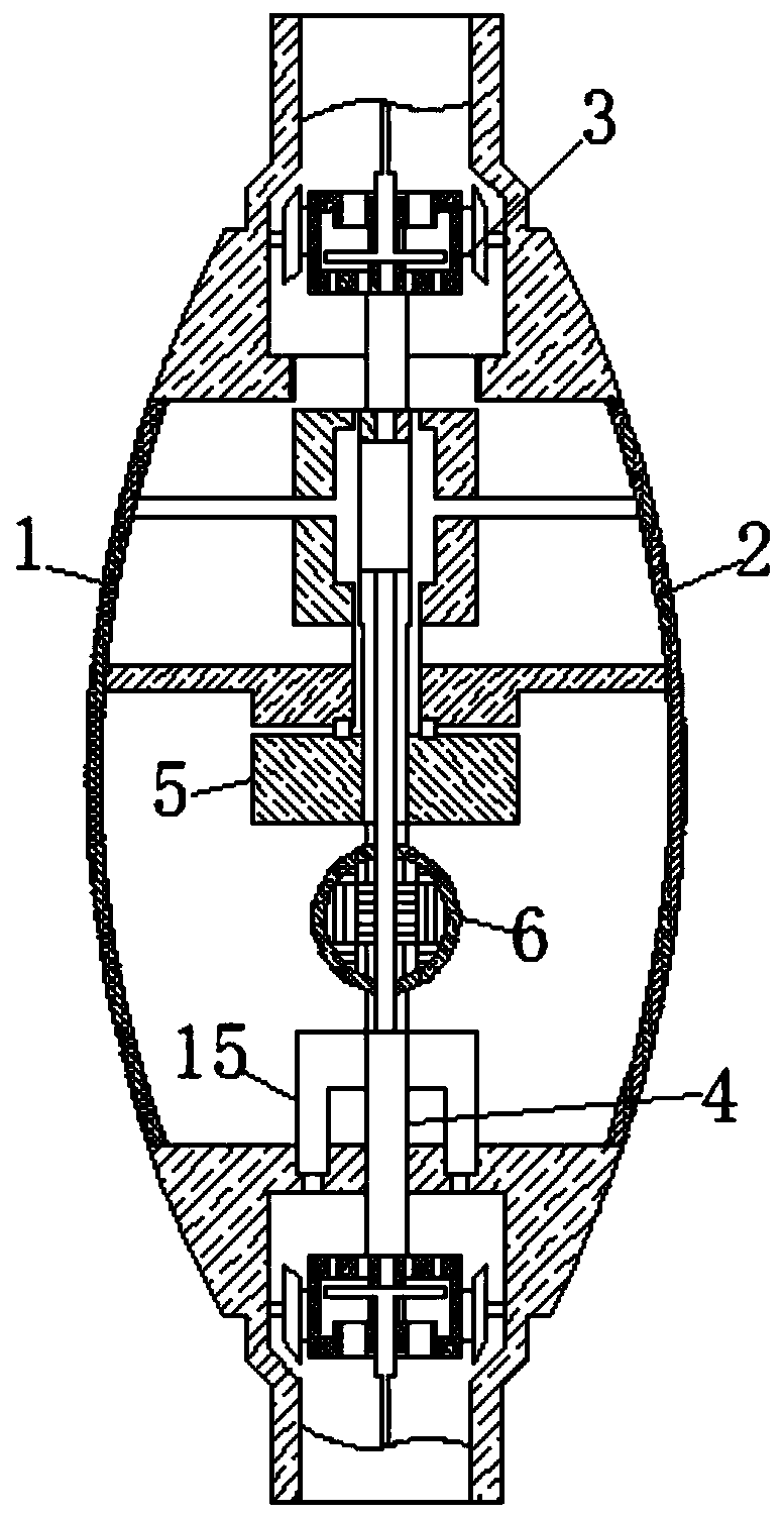
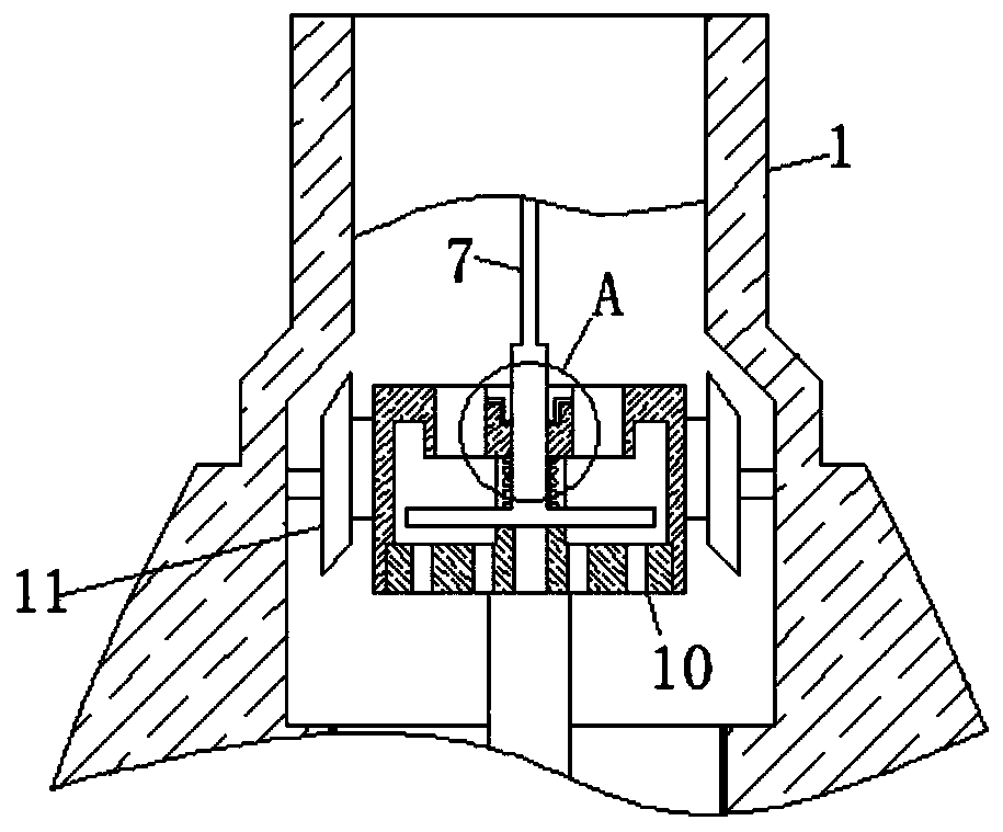
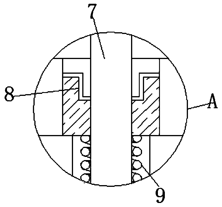
[0021] see Figure 1-4 , an auxiliary device for maintaining the hydraulic rod in a single-column hydraulic press, including a housing 1, the housing 1 is placed in the hydraulic machine, and combined with the hydraulic rod, when the hydraulic rod works for a period of time, due to its working The characteristics will cause friction with some parts in the mechanical equipment, and the continuous friction of the hydraulic rod will generate heat and consume part...


PUM


Abstract

The invention relates to the technical field of maintenance of hydraulic rods of hydraulic machines, and discloses auxiliary equipment for maintenance of a hydraulic rod in a hydraulic single column press. The auxiliary equipment comprises a shell; the interior of the shell is fixedly connected with sliding rails; the surfaces of the sliding rails are connected with a lubricating block in a sliding manner; the surface of the lubricating block is fixedly connected with a piston rod; the surface of the piston rod is connected with a lubricating mechanism in a sleeving manner; the position, position below the lubricating mechanism, of the surface of the piston rod is fixedly connected with a limiting ball; and the interior of the lubricating block is movably connected with an injection rod. Asphalt in the limiting ball is softened by heat to loss a limiting effect; the lubricating block moves reciprocally discontinuously along with the hydraulic rod on the surfaces of the sliding rails; lubricating oil in the injection rod is extruded, by the injection rod under the driving of the stretching and compressing of a spring, from a suction port to lubricate the surface of the lubricating block; another part of the lubricating oil flows out of an air hole in the surface of an overflow plate to lubricate the sliding rails on the surface of the lubricating block; and therefore, the effectof supplementing oil periodically without stopping work is achieved.

Description

technical field [0001] The invention relates to the technical field of maintenance of hydraulic rods of hydraulic machines, in particular to auxiliary equipment for maintenance of hydraulic rods in single-column hydraulic machines. Background technique [0002] Hydraulic machinery is equipment and tools that work through fluid energy. Commonly seen in heavy equipment; in such equipment, hydraulic oil is delivered at high pressure by a hydraulic pump to the actuators in the equipment. The hydraulic pump is driven by an engine or an electric motor. Control the hydraulic oil by manipulating various hydraulic control valves to obtain the required pressure or flow. [0003] At present, there are two ways to replenish oil for single-column hydraulic machines. One is to manually apply lubricating oil. Obviously, this method has low brushing efficiency. The other is mechanical oil replenishment. Most mechanical oil replenishment equipment It is necessary to configure a special mo...

Claims


Application Information

Patent Timeline
Patent Type & Authority Applications(China)
IPC IPC(8): F16N11/08F16N11/10
CPCF16N11/08F16N11/10F16N2270/22F16N2270/56F16N2270/70
Inventor 严有平
Owner 严有平
Learn More