Novel high-overload differential pressure sensor

A differential pressure sensor, high overload technology, applied in the field of measuring instruments, can solve the problems of unsatisfactory temperature compensation data of the sensor, unequal oil volume at both ends, sensor measurement error, etc., to achieve stable accuracy, reduction of oil filling, and removal of effect of stress

Pending Publication Date: 2020-05-15
盛雪梅
View PDF0 Cites 1 Cited by
  • Summary
  • Abstract
  • Description
  • Claims
  • Application Information

AI Technical Summary

Problems solved by technology

[0002] Existing differential pressure sensors include capacitive and single-crystal silicon types. The single-crystal silicon differential pressure sensor has the problem that the volumes of the oil passages at both ends are not equal. If the oil circuits are not equal, it is equivalent to applying positive or negative pressure to the monocrystalline silicon chip, causing sensor measurement errors and sensor temperature compensation data is not ideal
When the positive pressure end or the negative pressure end exerts a pressure much higher than the range, if the oil passages at both ends are not equal, the monocrystalline silicon chip will also be impacted, thereby damaging the sensor

Method used


Image

  • Novel high-overload differential pressure sensor
  • Novel high-overload differential pressure sensor

Examples


Embodiment Construction

[0024] A new type of high overload differential pressure sensor provided by the present invention will be further described in detail below with reference to the accompanying drawings and specific embodiments.

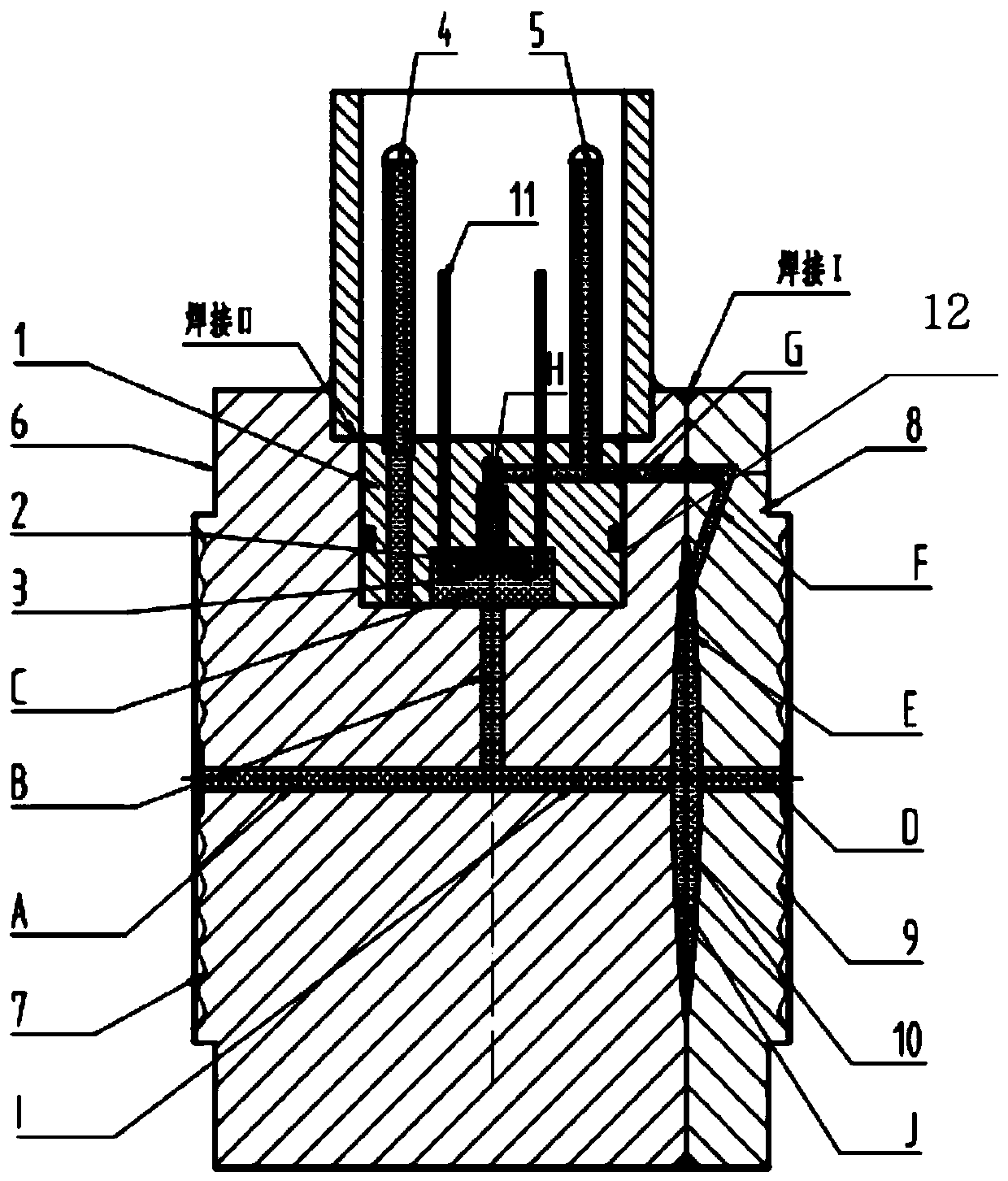
[0025] Such as figure 1 As shown, a new type of high overload differential pressure sensor provided by the present invention includes a chip base 1, a single crystal silicon differential pressure chip 2, a gold wire 3, a positive pressure end oil filling tube 4, a negative pressure end oil filling tube 5, a positive pressure Base 6, positive pressure isolation diaphragm 7, negative pressure base 8, negative pressure isolation diaphragm 9, center overload diaphragm 10, pin 11, fluorine rubber ring 12;

[0026] The chip base 1 is sintered, and the single crystal silicon differential pressure chip 2 is glued inside. The single crystal silicon differential pressure chip 2 is connected to the pin 11 on the chip base 1 through the gold wire 3, thereby realizing the chip base...


PUM

PropertyMeasurementUnit
temperatureaaaaaaaaaa
electrical resistanceaaaaaaaaaa
electric potential / voltageaaaaaaaaaa

Abstract

The invention belongs to the technical field of measuring instruments, and particularly relates to a novel high-overload differential pressure sensor. A chip base is installed in a groove in the center of the top of a positive pressure base, and a monocrystalline silicon differential pressure chip is bonded to the interior of the chip base; two oil filling pipes are sintered on the chip base and are divided into a positive pressure end oil filling pipe and a negative pressure end oil filling pipe; oil ways are formed in the positive pressure base and the negative pressure base, a central overload membrane is installed between the negative pressure base and the positive pressure base, the oil ways in the positive pressure base and the negative pressure base are divided into the positive pressure oil way and the negative pressure oil way, and the volume of the positive pressure oil way is equal to that of the negative pressure oil way. The positive pressure oil way cavity is filled withsilicone oil through the positive pressure end oil filling pipe, the negative pressure oil way cavity is filled with silicone oil through the negative pressure end oil filling pipe, and after oil filling is completed, the positive pressure end oil filling pipe and the negative pressure end oil filling pipe are blocked and sealed through argon arc welding. The volumes of the positive pressure end and the negative pressure end are ensured to be equal so that the precision of the monocrystalline silicon differential pressure chip is stable and the stability of the sensor is improved.

Description

technical field [0001] The invention belongs to the technical field of measuring instruments, in particular to a novel high-overload differential pressure sensor, in particular to a high-overload differential pressure sensor with inclined holes, a central overload diaphragm hard seal, and equal oil passages. Background technique [0002] Existing differential pressure sensors include capacitive and single-crystal silicon types. The single-crystal silicon differential pressure sensor has the problem that the volumes of the oil passages at both ends are not equal. If the oil paths are not equal, it is equivalent to applying positive or negative pressure to the monocrystalline silicon chip, causing sensor measurement errors and sensor temperature compensation data is not ideal. When a pressure much higher than the range is applied on the positive pressure end or the negative pressure end, if the oil passages at both ends are not equal, the single crystal silicon chip will also ...

Claims


Application Information

Patent Timeline
Patent Type & Authority Applications(China)
IPC IPC(8): G01L13/02G01L19/06
CPCG01L13/026G01L19/0618
Inventor 盛雪梅
Owner 盛雪梅
Why Eureka
Try Eureka